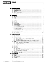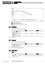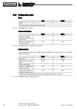
Fig. 1 Maximum relative humidity .........................................................................................................
5
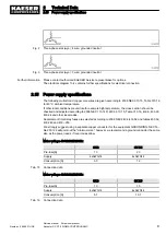
Fig. 2 Three-phase star (wye); 4 wire; grounded neutral .....................................................................
9
Fig. 3 Three-phase star (wye); 3 wire; grounded neutral .....................................................................
9
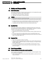
Fig. 4 Location of safety signs ..............................................................................................................
16
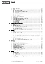
Fig. 5 Enclosure ...................................................................................................................................
20
Fig. 6 Machine layout ...........................................................................................................................
21
Fig. 7 Refrigeration Dryer .....................................................................................................................
22
Fig. 8 Air receiver .................................................................................................................................
22
Fig. 9 Machine mountings ....................................................................................................................
23
Fig. 10 Microfilter ....................................................................................................................................
24
Fig. 11 Activated carbon filter .................................................................................................................
24
Fig. 12 Keys ...........................................................................................................................................
27
Fig. 13 Indicators ....................................................................................................................................
28
Fig. 14 Recommended machine placement and dimensions [in] ...........................................................
32
Fig. 15 Compressed air connection ........................................................................................................
35
Fig. 16 Condensate drain dimensions [inch] ..........................................................................................
36
Fig. 17 Connections to SIGMA CONTROL BASIC ...............................................................................
37
Fig. 18 Hot gas bypass valve adjustment for altitude .............................................................................
41
Fig. 19 Adjustment angle ........................................................................................................................
41
Fig. 20 Inlet valve filling port ...................................................................................................................
42
Fig. 21 Interlock switch position .............................................................................................................
44
Fig. 22 Switching on and off ...................................................................................................................
46
Fig. 23 Switching off in an emergency ...................................................................................................
47
Fig. 24 Acknowledging messages ..........................................................................................................
48
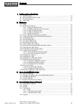
Fig. 25 Filter mat for the air and oil cooler ..............................................................................................
56
Fig. 26 Control cabinet ventilation grill ...................................................................................................
57
Fig. 27 Filter mat for air and oil cooler ....................................................................................................
58
Fig. 28 Air filter maintenance ..................................................................................................................
59
Fig. 29 Changing the belt .......................................................................................................................
60
Fig. 30 Checking the cooling oil level .....................................................................................................
62
Fig. 31 Venting the machine ...................................................................................................................
63
Fig. 32 Topping up the Cooling Oil .........................................................................................................
65
Fig. 33 Changing the cooling oil, oil separator tank ...............................................................................
67
Fig. 34 Changing the cooling oil, oil cooler .............................................................................................
69
Fig. 35 Changing the oil filter ..................................................................................................................
70
Fig. 36 Changing the oil separator cartridge ..........................................................................................
71
Fig. 37 Refrigeration dryer ......................................................................................................................
72
Fig. 38 Checking condensate drainage ..................................................................................................
73
Fig. 39 Condensate drain maintenance .................................................................................................
74
Fig. 40 Condensate drain tap .................................................................................................................
75
Fig. 41 Testing the safety relief valve .....................................................................................................
75
Fig. 42 Transporting with a forklift ..........................................................................................................
82
Fig. 43 Transporting with a crane ...........................................................................................................
83
List of Illustrations
Number: 9_6945 01USE
Service manual Screw compressor
Aircenter SX 3/7.5 SIGMA CONTROL BASIC
v

