background image

46

O

p

era

ti

n

g

 o

the

r d

e

vi

ce

us

in

g

 t

h

e re

mo

te

 c

o

nt

rol

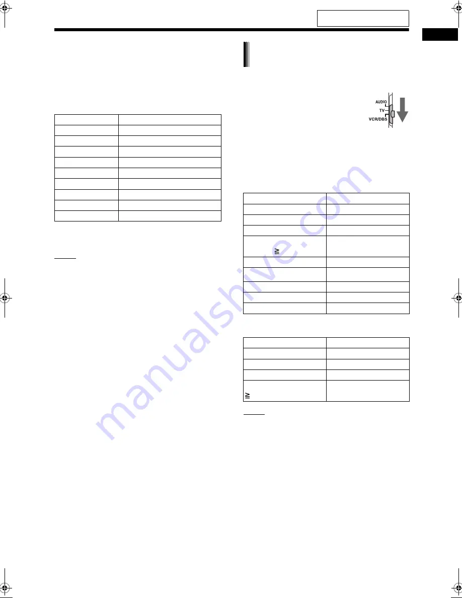
Manufacturer codes for DBSs
Examples: 

For an Echostar DBS: Press [2], then [1]. 
For a Sony DBS: Press [2], then [0]. 
When the manufacturer of your DBS has 2 or more 
codes, select the manufacturer codes in turn and 
find the one that operates the DBS and the remote 
control properly.


6

Release [VCR/DBS 

F

]. 

NOTE

• Manufacturer codes are subject to change with-

out notice. You may not be able to operate the 
VCR/DBS produced by the manufacturer. 

• After replacing the batteries of the remote con-

trol, set the manufacturer code again. 

Before the VCR/DBS operation, select the remote 
control mode for the VCR/DBS. 

1

Slide the remote control 
mode selector to [VCR/
DBS].

2

Press [VCR] or [DBS]. 

Operate the remote control by pointing it at the 
VCR/DBS.

Remote control button assigned for the VCR 
operation

Remote control button assigned for the DBS 
operation

NOTE

• When the remote control mode selector is slid to 

[VCR/DBS], some buttons may not work. 

Manufacturer

Code

G. I.

01, 02, 03, 04, 05, 06, 07, 08

Echostar

21

Hamlin

15, 16, 17, 18

Jerrold

01, 02, 03, 04, 05, 06, 07, 08

Pioneer 13, 

14

RCA

19

Scientific Atlanta

09, 10

Sony

20

Zenith

11, 12

Remote control button Usage

[VCR/DBS 

F

]

Turns on/off the VCR.

[VCR]

Selects the VCR input.

[TV C/

]

Changes channels.

Number buttons 
(1-10, 0,  10)

Selects the channels.

[DVD/CD 

3

]

Starts playback.

7


Stops playback.

8

 Pauses 

playback.

¡


Fast-forwards the tape.

1

 Fast-rewinds 

the 

tape. 

Remote control button Usage

[VCR/DBS 

F

]

Turns on/off the DBS.

[DBS]

Selects the DBS input.

[TV C/

]

Changes channels.

Number buttons (1-9, 0, 

10)

Selects the channels.

Using the remote control for the 
VCR/DBS operation

For the locations of the remote 
control buttons, refer to page 44.

DD-831[A_Ux]-09.fm  Page 46  Friday, September 8, 2006  12:28 PM

Summary of Contents for CA-DD3

Page 1: ... which are located either on the rear bottom or side of the cabinet Retain this information for future reference Model No Serial No LVT1546 001A J DD 8 Consists of CA DD8 SP PWDD8 SP DD8F and SP DD8S Se compose de CA DD8 SP PWDD8 SP DD8F et SP DD8S DD 3 Consists of CA DD3 SP PWDD3 SP DD3F and SP DD8S Se compose de CA DD3 SP PWDD3 SP DD3F et SP DD8S ...

Page 2: ...f the following measures Reorient or relocate the receiving antenna Increase the separation between the equipment and receiver Connect the equipment into an outlet on a circuit different from that to which the receiver is connected Consult the dealer or an experienced radio TV technician for help CAUTION Changes or modifications not approved by JVC could void the user s authority to operate the eq...

Page 3: ...cuée correctement de l appareil Ne placez aucune source de flamme nue telle qu une bougie sur l appareil Lors de la mise au rebut des piles veuillez prendre en considération les problèmes de l environnement et suivre strictement les règles et les lois locales sur la mise au rebut des piles N exposez pas cet appareil à la pluie à l humidité à un égouttement ou à des éclaboussures et ne placez pas d...

Page 4: ...ent Wall or obstructions Mur ou encombrement Front Façade No obstructions Pas d encombrement CAUTION F button CA DD8 CA DD3 Disconnect the mains plug to shut the power off completely the STANDBY lamp goes off When installing the apparatus ensure that the plug is easily accessible The F button in any position does not disconnect the mains line When the system is on standby the STANDBY lamp lights r...

Page 5: ...iche secteur pour mettre l appareil complètement hors tension le témoin POWER ON l s éteint Lors de l installation de l appareil assurez vous que la fiche soit facilement accessible Quand l appareil est sous tension le témoin POWER ON est allumé en vert CAUTION To avoid personal injury or accidentally dropping the unit have two persons unpack carry and install the unit ATTENTION Pour éviter toute ...

Page 6: ...2 Playing back a file 23 Display window on the main unit for disc file types 24 Stopping playback 27 Resuming playback 27 Pausing playback 27 Advancing the picture frame by frame 27 Fast reverse fast forward search 28 Playing back from a position 10 seconds before 28 Slow motion playback 28 Skipping to the beginning of a chapter track file 28 Selecting a chapter track using the number buttons 29 S...

Page 7: ...CA DD3 54 Subwoofer for DD 8 SP PWDD8 54 Subwoofer for DD 3 SP PWDD3 55 Left and right speakers for DD 8 SP DD8F 55 Left and right speakers for DD 3 SP DD3F 55 Center surround speaker SP DD8S 56 Supplied accessories 56 Playing back sources from other devices Operating other devices using the remote control Reference How to read this manual This manual explains operations assuming that you will use...

Page 8: ...isplay window During playback when you connect or disconnect headphones sound from the LINE OUT and LINE DIGITAL OUT terminals may be intermittent While recording sound to another device do not connect or disconnect headphones 2 Refer to the separate volume of the operation manual for the network function Refer to Display window shown below Front view These terminals are available when the front c...

Page 9: ...replace both batteries CAUTION Do not expose batteries to heat or flame Point the remote control directly at the front of the main unit Do not block the remote control sensor on the main unit Use the remote control at a position higher than the main unit Inserting the batteries into the remote control R6P SUM 3 AA 15F type dry cell batteries supplied Operating the system from the remote control Us...

Page 10: ...TE A coaxial cable is recommended as it reduces interference for FM reception Connecting the antennas AM loop antenna supplied If insulation covers the tips of the antenna cable twist and pull off the insulation Main unit rear view FM antenna supplied Main unit rear view FM antenna Stretch out the FM antenna horizontally Main unit rear view Outdoor FM antenna cable not supplied 75 Ω coaxial connec...

Page 11: ... installed on a wall Be sure to have the speaker installed on the wall by qualified personnel DO NOT install the speaker on the wall by your self to avoid unexpected damage from it falling off the wall due to incorrect installation or weak ness in wall structure Care must be taken in selecting a location for speaker installation on a wall Injury to personnel or damage to devices may result if the ...

Page 12: ...e left and right speakers are the same Black lines Black Gray Black Blue Black Rear view Gray Blue Left Right The speaker is shown assembled to the speaker stand on page 6 NOTE When connecting the speaker cable to the termi nal on the center surround speaker make sure that the end of speaker cable does not touch any other nearby metallic parts Right speaker SP DD8F Left speaker SP DD8F Center surr...

Page 13: ...he sheet from the bottom cover and then affix the bottom cover to the left right speaker DO NOT install the speakers on the wall by your self to avoid unexpected damage from them fall ing off the wall due to incorrect installation or weakness in wall structure Care must be taken in selecting a location for speaker installation on a wall Injury to personnel or damage to devices may result if the in...

Page 14: ...rround speaker SP DD8S Black lines Black Gray Black Blue Black Black Rear view Gray Blue Rear view Left Right The speaker is shown assembled to the speaker stand on page 8 NOTE When connecting the speaker cable to the termi nal on the center surround speaker make sure that the end of speaker cable does not touch any other nearby metallic parts Right speaker SP DD3F Left speaker SP DD3F Center surr...

Page 15: ... speakers are magnetically shielded but color irregularity may occur on the TV depending on some conditions To prevent color irregularity set up the speakers following the instructions below 1 Turn off the main power of the TV before setting up the speakers 2 Place the speakers enough distance from the TV so that they do not cause color irregularity on the TV 3 Wait for approximately 30 minutes be...

Page 16: ...posite video cable supplied Main unit rear view Connecting a TV with the S VIDEO terminal TV To an S video terminal S video cable not supplied Main unit rear view Connecting a TV with the COMPONENT VIDEO OUT terminals TV Main unit rear view To component terminals Component video cable not supplied Connecting a TV with the HDMI terminal Main unit rear view TV HDMI cable not supplied To an HDMI term...

Page 17: ... may not be played back properly Connect the main unit directly to a TV or a mon itor without routing through a video cassette recorder VCR Otherwise picture distortion may occur during playback Routing the con nection through a VCR however does not affect the audio quality Connecting the main unit to a VCR built in TV may also cause picture distortion during play back To view an image on the TV s...

Page 18: ...ow When an HD video signal 720p is output the HD indicator lights up When 480P or 720P is selected the PRO GRESSIVE indicator lights up in the display window 4 Press ENTER The selected video signal type is displayed in the display window for a short time NOTE The picture may be distorted when you press ENTER but this is not a malfunction of the sys tem To check the compatibility of your TV contact...

Page 19: ...TING 2 Press 5 or to select LINEOUT in the display window 3 Press 2 or 3 to select L1 or L2 L1 for normal usage the initial setting L2 for higher level Connecting a portable digital audio player Listening to analog sound from a portable digital audio player Main unit front view Input Output Portable digital audio player or other audio device Audio cable notsupplied To an audio output terminal Outp...

Page 20: ...unit rear view Optical digital cable not supplied Input MD player or satel lite receiver To an optical digital output terminal Output Connecting other analog audio devices Connecting the power cable Output Audio device Audio cable not supplied Input Main unit rear view Main unit rear view AC outlet Subwoofer rear view AC outlet Preparation continued Do not turn on the power until you complete the ...

Page 21: ...ing at the same time Press AUDIO VOL Adjustable volume range is from 0 to 40 You can also adjust the volume by pressing VOLUME on the main unit NOTE Refer to page 17 for adjusting the volume of the center surround speaker subwoofer Refer to page 17 for adjusting the volume bal ance between the left and right speakers Press MUTING Press MUTING again to restore the sound When the main unit is turned...

Page 22: ...peatedly select SURR the center sur round speaker or SUBWFR the subwoofer in the display window 2 Press or to adjust the vol ume NOTE Adjustable volume range is from 6 to 6 1 Press SETTING 2 Press 5 or to display BAL in the display window 3 Press 2 or 3 to adjust the volume balance CENTER the initial setting is displayed when the volume of the left and right speak ers are the same You can adjust t...

Page 23: ... off Press SLEEP Each time you press SLEEP the time indicated in the display window changes You can set the time to 10 20 30 60 90 120 or 150 minutes Example Display when the sleep timer is set to 60 minutes NOTE When the sleep timer is activated the display window becomes darker automatically Press SLEEP repeatedly to select the time again Press SLEEP once Press SLEEP repeatedly until SLEEP disap...

Page 24: ...ed out for 3 minutes the main unit automatically turns off NOTE Leaving the volume at 0 is not the same as producing no sound and therefore does not start the auto standby function You can lock the disc tray to prevent the disc from being ejected When the main unit is turned off Press 0 while holding down 7 on the main unit Repeat this step to cancel the disc ejection lock The display window chang...

Page 25: ...uning Automatic tuning Hold down TUNING or TUNING until the frequency starts changing and then release the button When the main unit has received a broad cast the frequency automatically stops changing You can select a specific radio station while searching for a broadcast Press TUN ING or TUNING to stop the automatic tuning when the desired frequency appears in the display window NOTE If an FM st...

Page 26: ...he selected number is flash ing press MEMORY or ENTER STORED appears and the selected radio station is stored NOTE When you store a radio station to a preset num ber to which another radio station has previously been stored the newly set radio station replaces the previously stored radio station You can also use 2 or 3 to select the preset number in step 3 When an FM or AM radio broadcast is selec...

Page 27: ...the buttons on the main unit Repeatedly pressing SOURCE can select the disc as the source and pressing 3 starts playback A menu screen may appear on the TV screen after DVD playback starts In such a case oper ate the menu screen referring to Selecting a track from the menu screen on page 29 If you perform an operation such as changing the source quickly or loading an incompatible disc refer to pag...

Page 28: ... routing through a USB hub Otherwise a malfunction may occur Before disconnecting the USB mass storage class device make sure that playback is stopped The main unit does not charge a USB mass stor age class device connected to the USB termi nal 2 Press DVD CD 3 or USB 3 NOTE You can also use the buttons on the main unit Repeatedly pressing SOURCE can select the disc file as the source and pressing...

Page 29: ... a disc is stopped When a disc is played back You can control the playback of a PBC compati ble disc using a menu screen To cancel the PBC function follow the instruc tions below Specify the track number using the number buttons when the disc is stopped Specify the track number using 4 or when the disc is stopped and then press DVD CD 3 Press RETURN to go back to the upper layer during PBC playbac...

Page 30: ... WAV ASF DivX MPEG1 MPEG2 file Group number Track number Elapsed playback time File type Group number Track number JPEG file File type Group number File number Messages on the TV screen When a DVD VIDEO is selected as the source the messages shown below are displayed on the TV screen to indicate the disc status NOW READING Appears when the main unit is reading the disc information Wait for a short...

Page 31: ...put signal is processed using DOLBY DIGITAL PRO LOGIC II The input signal is DTS The input signal is LPCM The sound is produced from the sub woofer The or indicator in the frame shows the speaker produc ing the sound The input signal is for the left speaker The input signal is for the center surround speaker The input signal is for the right speaker The input signal is LFE The input signal is for ...

Page 32: ...is function does not work in program playback or random playback You can deactivate the resume playback func tion Refer to RESUME on page 39 Press 7 twice NOTE The stored position is also cleared if the disc tray is opened When a disc file is played back Press 8 Press DVD CD 3 or USB 3 to return to the normal playback When a disc file is paused Press 8 repeatedly Stopping playback Resuming playbac...

Page 33: ...e previous title When a disc is paused Press SLOW or SLOW Each time you press SLOW or SLOW the speed increases Pressing DVD CD 3 cancels this function and starts normal playback NOTE No sound is produced The picture motion in the reverse direction may not be smooth For a VCD or SVCD slow motion playback can be used in the forward direction only When a disc file is played back Press 4 or repeatedly...

Page 34: ...stopped or played back 1 Press MENU or TOP MENU The menu screen is displayed 2 Press 5 2 3 or the number buttons to select the desired track 3 Press ENTER NOTE You can use this function only when a menu screen is recorded on the disc For a VCD SVCD MENU and TOP MENU may be unavailable in step 1 In this case press RETURN once or more For a VCD SVCD you cannot use 5 2 or 3 in step 2 For a VCD SVCD w...

Page 35: ... can only select these function settings when the disc file contains multiple audio languages subtitle languages or view angles When a language code such as AA and AB is displayed refer to Language codes on page 40 You can also use the menu bar to set the func tions Refer to page 35 ST L and R displayed when playing back a VCD or SVCD respectively indicate Stereo Left sound and Right sound Number ...

Page 36: ...e tracks in the selected group are programmed You can erase the programmed tracks one by one from the bottom of the list on the program screen by pressing CANCEL repeatedly You can erase the whole program at once by pressing 7 Ejecting the disc or turning off the main unit also erases the program 3 Press DVD CD 3 When a disc file is played back Press 7 Playback stops and the program screen appears...

Page 37: ... random playback When a disc is played back or paused 1 Press ZOOM Each time you press the button the picture magnification changes in the display win dow 2 Select the portion you want to magnify by using 5 2 or 3 To return to normal playback select ZOOM x 1 in step 1 NOTE When you magnify a picture image quality may be deteriorated or the image may be distorted Playing back a disc file in a rando...

Page 38: ...r than the one with the WIDE 2chMUSIC is produced SURROUND OFF Turns off the surround sound NOTE When a surround processed signal is input while AUTO SURROUND MOVIE M MUSIC WIDE 2chMUSIC or SUPER WIDE is selected the SURROUND indicator in the dis play window lights up Depending on the signal type surround sound may not be produced as the surround mode set ting During playback when you change the s...

Page 39: ... and light portions Selectable options LOW MID and HIGH BRIGHTNESS Controls the brightness of the display Setting range 8 to 8 CONTRAST Controls the contrast of the display Set ting range 12 to 12 SATURATION Controls the saturation of the display Set ting range 16 to 16 TINT Controls the tint of the display Setting range 16 to 16 SHARPNESS Controls the sharpness of the display Selectable options L...

Page 40: ...Time display selection Changes the time information in the display window and the status bar Each time ENTER is pressed the display changes on the menu bar DVD VIDEO operating during play back TOTAL Elapsed playback time of the current title T REM Remaining time of the cur rent title Time Elapsed playback time of the current chapter REM Remaining time of the cur rent chapter CD operating during pl...

Page 41: ... 1 Press ON SCREEN twice The menu bar appears Refer to page 35 2 Press 2 or 3 to select 3 Press ENTER 4 Enter the time using the number buttons Example When you want to play back a DVD VIDEO from the position of 0 hour 23 minutes 45 seconds press the number buttons in the order of 0 2 3 4 and 5 You can skip entering the minute and sec ond settings If the incorrect value is entered press 2 to delet...

Page 42: ...TV screen Example 2 Use 5 2 3 and ENTER to control the preference screen Proceed with operations by following the description on the TV screen NOTE If the selected language is not recorded on the disc file the optimum language set for the disc file is displayed For a language code such as AA refer to the Language codes on page 40 Remote control mode selector Basic operations LANGUAGE Items Content...

Page 43: ...EN SAVER You can turn or OFF the screen saver The screen saver activates when there is no operation made for approxi mately 5 minutes since a still picture was last displayed NOTE This function does not work when this system outputs the video signal via the HDMI terminal FILE TYPE When files of different types are recorded on a disc or connected USB mass stor age class device select the file type ...

Page 44: ...e audio signal from the HDMI terminal is output ON The audio signal from the HDMI is out put The audio signal from the HDMI is not output NOTE Depending on the connected TV when HDMI AUDIO OUT is set to ON only PCM signals can be output via an HDMI cable STREAM PCM STEREO NORMAL OFF OTHERS Items Contents initial setting RESUME Select or OFF Refer to page 27 ON SCREEN GUIDE Select or OFF Refer to p...

Page 45: ...sa MO Moldavian SQ Albanian AS Assamese HI Hindi MR Marathi SR Serbian AY Aymara HR Croatian MS Malay MAY SS Siswati AZ Azerbaijani HU Hungarian MT Maltese ST Sesotho BA Bashkir HY Armenian MY Burmese SU Sundanese BE Byelorussian IA Interlingua NA Nauru SV Swedish BG Bulgarian IE Interlingue NE Nepali SW Swahili BH Bihari IK Inupiak NL Dutch TA Tamil BI Bislama IN Indonesian NO Norwegian TE Telugu...

Page 46: ...ted device 3 Adjust the volume and make other necessary settings Refer to Basic operations on page 16 You can select the gain of the signal from the LINE IN 1 and LINE IN 2 terminals Use the initial settings for normal operation If the sound is too small or too loud change the settings 1 Press LINE repeatedly to select LINE 1 or LINE 2 in the display window 2 Hold down ENTER Each time you hold dow...

Page 47: ... player is automatically selected LINE 1 is displayed and sound is produced NOTE 1 When QP ON is displayed ACT or NO ACT is also displayed to indicate the status of QP LINK According to the status of the main unit ACT and NO ACT changes automati cally QP ON ACT is displayed when QP LINK is activated and available QP ON NO ACT is displayed when QP LINK is activated but unavailable Pressing QP LINK ...

Page 48: ...odes select the manufacturer codes in turn and find the one that operates the TV and the remote control properly 5 Release TV F NOTE Manufacturer codes are subject to change with out notice You may not be able to operate the TV produced by the manufacturer After replacing the batteries of the remote con trol set the manufacturer code again Operating a TV using the remote control Manufacturer Code ...

Page 49: ...codes in turn and find the one that operates the VCR and the remote control properly Remote control button Usage TV F Turns on off the TV TV VIDEO Changes between the TV and video input TV CHANNEL Changes channels TV VOL Adjusts volume Number but tons 1 9 0 100 Slide the remote control mode selector to TV in advance Selects the channels TV RETURN Changes between the previously selected chan nel an...

Page 50: ... Remote control button assigned for the VCR operation Remote control button assigned for the DBS operation NOTE When the remote control mode selector is slid to VCR DBS some buttons may not work Manufacturer Code G I 01 02 03 04 05 06 07 08 Echostar 21 Hamlin 15 16 17 18 Jerrold 01 02 03 04 05 06 07 08 Pioneer 13 14 RCA 19 Scientific Atlanta 09 10 Sony 20 Zenith 11 12 Remote control button Usage V...

Page 51: ... manual of the TV to be con nected to the main unit The AV COMPU LINK function may not work for some TVs when the main unit is connected to the video 2 or video 3 terminal on the TV 1 Turn on the main power of the TV 2 Play back a disc file Refer to pages 22 24 The power of the TV is turned on The input mode on the TV changes to the video 1 video 2 or video 3 DVD input NOTE You can use this functi...

Page 52: ...a soft dry cloth CAUTION Do not wipe the operation panel with thinners benzenes or other chemical agents Do not spray insecticides onto the operation panel These may cause discoloration and damage to the surface Manufactured under license from Dolby Labora tories Dolby and the double D symbol are trademarks of Dolby Laboratories DTS and DTS Digital Surround are registered trademarks of Digital The...

Page 53: ...ar a heating equipment When you are away When away on travel or for other reasons for an extended period of time disconnect the power cord plug from the wall outlet Do not block the vents Blocking the vents may damage the system Care of the cabinet When cleaning the system use a soft cloth and fol low the relevant instructions on the use of chemi cally coated cloths Do not use benzene thinner or o...

Page 54: ... for use with the NTSC standard Region code of DVD VIDEO DVD VIDEO players and DVD VIDEO discs have their own Region Code numbers This system can play back a DVD VIDEO whose Region Code number includes the system s Region Code which is indicated on the rear panel If a DVD VIDEO with an improper region code number is loaded REGION CODE ERROR appears on the TV screen and playback cannot start On som...

Page 55: ...ck in alphabetical order a commercially available MP3 WMA disc may be played back in an order different from that indi cated on the label attached to the disc Playing back an MP3 WMA file including a still image may take a long time The elapsed time is not displayed until playing back starts If playing back starts the elapsed time may not be dis played correctly For an MP3 WMA file a disc with a s...

Page 56: ...x 480 352 x 240 pixels 30 fps The profile and level should be MP ML Main Profile at Main Level SP ML Simple Profile at Main Level MP LL Main Profile at Low Level Audio streams should conform to MPEG1 Audio Layer 2 MPEG2 Audio Layer 2 or Dolby Digital MPEG2 only The Non DVD side of a DualDisc does not com ply with the Compact Disc Digital Audio standard Therefore the use of Non DVD side of a DualDi...

Page 57: ...he tracks files with numbers exceeding 150 and the groups with num bers exceeding 99 these cannot be played back If there are any type of files other than MP3 WMA WAV JPEG ASF DivX MPEG1 MPEG2 files on a disc those files are also counted in the total file number Do not use any non standard shape disc like a heart flower or credit card etc available on the market because it may damage the system Do...

Page 58: ...re is distorted when the TV is con nected to the HDMI ter minal The proportion of the picture is not appropriate Connect the TV to the VIDEO ter minal or S VIDEO terminal and select the video signal type and the monitor out type 11 13 A radio broadcast can not be received No antenna is connected Connect an antenna 5 A whirring noise is pro duced The main unit is located close to a TV computer or o...

Page 59: ... antenna terminal x 1 Ethernet terminal x 1 HDMI monitor output terminal x 1 USB Compatible with USB 2 0 Full Speed Compatible device Mass storage class device Compatible file system FAT16 FAT32 Bus power supply Max 500 mA General Power source AC 120 V 60 Hz Power consumption in operation 25 W Power consumption on standby 0 5 W Dimensions W x H x D 445 mm x 55 mm x 286 4 mm 17 x 2 x 11 including p...

Page 60: ...2 2 cm dome Power handling capacity 30 W Impedance 3 Ω Frequency range 60 Hz 40 kHz Sound pressure level 81 dB W m Dimensions W x H x D 289 mm x 1 101 mm x 289 mm 11 x 3 7 x 11 Weight 1 unit 10 0 kg 22 1 lbs Type 2 way acoustic suspension type Magnetically shielded type Speaker 9 5 cm 3 x 1 cm direct drive 2 cm dome Power handling capacity 30 W Impedance 3 Ω Frequency range 100 Hz 40 kHz Sound pre...

Page 61: ...rround speaker cable x 1 System cable x 1 Composite video cable x 1 M4 x 25 mm 1 screw for the stands of the left and right speakers x 6 Only for DD 8 M4 x 16 mm screw for the stands of the left and right speakers x 6 Only for DD 3 M5 x 14 mm screw for the stands of the center surround speaker x 2 Bottom cover of the left and right speakers for wall installation x 2 Only for DD 3 Main volume of th...

Page 62: ...For U S A ...

Page 63: ...For U S A ...

Page 64: ...1006SKMMODJEM 2006 Victor Company of Japan Limited EN FR c ...

Page 65: ...OLUME INSTRUCTIONS FOR NETWORK FUNCTION REGISTRE SEPARÉ INSTRUCTIONS POUR LA FONCTION RÉSEAU LVT1547 001A J DD 8 DD 3 This manual explains the network function of this system Ce manuel explique les fonctions réseau de ce système ...

Page 66: ...ite for details http www dlna org CyberLink Media Server is a registered trademark along with other company and product names mentioned in this publication used for identification purposes and remain the exclusive property of their respective own ers DLNA and DLNA CERTIFIED are trademarks and or service marks of Digital Living Network Alliance Microsoft Windows Windows XP are registered trademarks...

Page 67: ...rLink Media Server 9 Setting up the IP address 11 Occasions requiring the IP address setup 11 Determining the IP address of the computer 11 Assigning the IP address to the main unit 13 Playing back files stored on the computer 16 Playing back audio files 16 Reference 18 Adding shared folders 18 Connecting the main unit to the computer directly 19 Troubleshooting 20 Introduction Connection Installi...

Page 68: ...nit The DHCP function of the router automatically assigns the IP address to the main unit NOTE If the router does not have a DHCP function or you do not use the DHCP function you must assign the IP address to the main unit manually You can also use the network function by con necting the main unit to the computer directly Refer to page 19 You can play back the following file types using the networ...

Page 69: ... 10 Page 10 Page 11 Page 13 Page 16 Page 8 Start CyberLink Media Server and then make sure that the main unit recognizes CyberLink Media Server Make sure that the main unit is turned on Check the cable connection The IP address has to be set up manually Exit CyberLink Media Server Find out the IP address of your computer Assign the IP address to the main unit The setup is complete Now you can enjo...

Page 70: ... RAM Requirement 256 MB Recommendation 512 MB Free hard disk space Requirement 50 MB Recommendation 200 MB Network Interface Card Requirement Ethernet 802 3 or WiFi 802 11a or 802 11g network adapter VGA Requirement Intel nVidia or ATI VGA card with 64 MB VRAM Make sure that there is an available LAN terminal on the router Also make sure that there is an available Ethernet cable straight through c...

Page 71: ...cting the main unit to the computer linked to the Internet via a router The diagram shown above has been simplified by omitting the connection of the main unit speakers and a TV Refer to the main volume of the operation manual for connecting the devices shown above The diagrams of the Internet and modem are omitted in the later explanations 1 Connect one end of the Ethernet cable straight through ...

Page 72: ...fter installing CyberLink Media Server from the supplied CD ROM it is recommended that you upgrade CyberLink Media Server to enable you to utilize the latest functions Refer to the web site http www victor co jp english download index e html for upgrading CyberLink Media Server On the computer 1 Start up Windows and place the CyberLink Media Server Software CD ROM into your computer s CD ROM drive...

Page 73: ...can store files of different types in one folder For example even when video files and still picture files are stored in the My Music folder you can play back those files 3 Click View Sharing 4 Confirm that the names of the shared folders are displayed on the list NOTE To stop sharing a folder Clear the check box next to it and click Apply To go back to the previous screen Click in the upper left ...

Page 74: ... control 1 Press F AUDIO to turn on the main unit On the computer 2 Double click the CyberLink Media Server icon on the desktop CyberLink Media Server starts On the remote control 3 Press NETWORK 3 4 Confirm that CyberLink Media Server is displayed on the TV screen Proceed to Playing back files stored on the computer on page 16 Starting CyberLink Media Server TV CyberLink Media Server Confirming t...

Page 75: ...er on page 6 to check that the Ether net cable is a straight through cable and is connected securely B You may be using a router that requires the IP addresses to be set up manually Possible cause The router connected to the main unit may not have a DHCP function that assigns the IP addresses automatically Another possi bility is that the IP addresses may be assigned manually without using the DHC...

Page 76: ... the procedure for determining the IP address of the computer by displaying the network setup NOTE Depending on the computer settings you may need operations different from the explanation given in this part Refer to Help in Windows for the following steps On the computer 1 Click Start and then Control Panel The Control Panel dialog box is displayed Occasions requiring the IP address setup Manual ...

Page 77: ...twork Connec tions icon and then proceed to step 4 3 Click Network Connections The Network Connections dialog box is displayed 4 Right click the Local Area Con nection icon and then click Prop erties The Local Area Connection Properties dialog box is displayed 5 Click Internet Protocol TCP IP and then click Properties The Internet Protocol TCP IP Properties dialog box is displayed Continued on the...

Page 78: ...ting up the IP address of the main unit manually You can skip this part when the main unit and the computer are connected to a router using a DHCP function NOTE Before assigning the IP address to the main unit press NETWORK 3 to select the connected computer as the source NETWORK SETUP on the preference screen is disabled when another source is selected On the remote control 1 Slide the remote con...

Page 79: ... SETUP and then press ENTER 5 Select OBTAIN IP and then press ENTER 6 Press 5 or to select STATIC IP and then press ENTER NOTE When changing the Internet connection environ ment by using a DHCP router or other devices that assign IP addresses automatically select DHCP for OBTAIN IP 7 Press to select STATIC IP ADDRESS and then press ENTER Continued on the next page TV ...

Page 80: ...nter the subnet mask using the number buttons Confirm the subnet mask you have written down in the column on page 13 and then enter the same value Example for setup 12 Press ENTER 13 Press to select APPLY NOW and then press ENTER The settings are stored You have finished setting up the IP address of the main unit Return to page 8 NOTE Usually you do not have to set DEFAULT GATEWAY For normal usage...

Page 81: ... part explains the procedure for playing back the TRACK0001 file stored in the My Music folder as an example Refer to the main volume of the operation man ual for details on operating the main unit On the computer 1 Start CyberLink Media Server On the remote control 2 Press NETWORK 3 CyberLink Media Server is displayed 3 Press to select CyberLink Media Server Continued on the next page Playing bac...

Page 82: ...ant to play back are stored in the shared folder 7 Press 5 or to select the file you want to play back 8 Press ENTER Playback starts Press 7 to stop playback NOTE You can use the buttons shown below to navi gate among the pages Pressing 2 or 3 displays the previous or next page Pressing 1 or skips 10 pages forward or backward Pressing 4 or skips to the top or bottom of the folder file list This pa...

Page 83: ...lder in the default My Videos folder and adding the DATA folder to the shared fold ers as examples 1 Store the DATA folder in the My Videos folder using Windows 2 Double click the CyberLink Media Server icon on the desktop CyberLink Media Server starts 3 Click My Videos 4 Select the check box next to DATA and click Apply 5 Click View Sharing 6 Confirm that the DATA folder is added to the list of s...

Page 84: ...y Select DHCP and then click ENTER in step 6 on page 14 DHCP is selected as the initial setting The main unit and the computer start to obtain the IP addresses recognizable by each other Wait about one minute until the setup is complete NOTE You can also assign arbitrary values for the IP addresses by following pages 11 to 15 4 Confirm the connection to the computer Set up the shared folders refer...

Page 85: ...ed Check that the same values are set in the first second and third group of digits and dif ferent values are set in the fourth group of digits for the main unit and the computer 11 15 A file is not played back properly Another device is using the network connected to the main unit If another device is using the network while the main unit is playing back a file the net work may be confused image ...

Page 86: ...1106SKMMODJEM 2006 Victor Company of Japan Limited EN FR c ...

Page 87: ...CTIONS LVT1546 009B A US UB UW UX DD 8 Consists of CA DD8 SP PWDD8 SP DD8F and SP DD8S DD 3 Consists of CA DD3 SP PWDD3 SP DD3F and SP DD8S DD 1 Consists of CA DD1 SP PWDD1 SP DD1F and SP DD1S DIGITAL MEDIA SYSTEM Only for DD 8 and DD 3 ...

Page 88: ...l be placed on the apparatus IMPORTANT FOR LASER PRODUCTS 1 CLASS 1 LASER PRODUCT 2 CAUTION Do not open the top cover There are no user serviceable parts inside the unit leave all servicing to qualified service personnel 3 CAUTION Visible and or invisible class 1M laser radiation when open Do not view directly with optical instruments 4 REPRODUCTION OF LABEL CAUTION LABEL PLACED INSIDE THE UNIT CA...

Page 89: ...s turned on the STANDBY lamp goes off The power can be remote controlled CAUTION SP PWDD8 SP PWDD3 SP PWDD1 The power supply to the subwoofer is linked to the center unit Disconnect the mains plug to shut the power off completely the POWER ON lamp goes off When installing the apparatus ensure that the plug is easily accessible When the system is turned on the POWER ON lamp lights green CAUTION To ...

Page 90: ...ack a disc 23 Playing back a file 24 Display window on the main unit for disc file types 25 Stopping playback 28 Resuming playback 28 Pausing playback 28 Advancing the picture frame by frame 28 Fast reverse fast forward search 29 Playing back from a position 10 seconds before 29 Slow motion playback 29 Skipping to the beginning of a chapter track file 29 Selecting a chapter track using the number ...

Page 91: ...F 55 Center surround speaker for DD 8 DD 3 SP DD8S 56 Center surround speaker for DD 1 SP DD1S 56 Supplied accessories 56 Playing back sources from other devices Operating other devices using the remote control Reference How to read this manual This manual explains operations assuming that you will use the remote control Some buttons on the main unit are the same as those on the remote control You...

Page 92: ...the LINE OUT and LINE DIGITAL OUT terminals may be intermittent While recording sound to another device do not connect or disconnect headphones 2 For DD 8 DD 3 users Refer to the separate volume of the operation manual for the network function For DD 1 users The LAN terminal is not available 3 For DD 8 DD 3 users Refer to page 12 For DD 1 users The HDMI terminal is not available Refer to Display w...

Page 93: ...o heat or flame Point the remote control directly at the front of the main unit Do not block the remote control sensor on the main unit Use the remote control at a position higher than the main unit DD 8 DD 3 DD 1 1 Refer to the separate volume of the opera tion manual for the network function Refer to page 19 2 Refer to page 19 No button Inserting the batteries into the remote control R6P SUM 3 A...

Page 94: ... coaxial cable is recommended as it reduces interference for FM reception Connecting the antennas AM loop antenna supplied If insulation covers the tips of the antenna cable twist and pull off the insulation Main unit rear view FM antenna supplied Main unit rear view FM antenna Stretch out the FM antenna horizontally Main unit rear view Outdoor FM antenna cable not supplied 75 Ω coaxial connector ...

Page 95: ...stalled on a wall Be sure to have the speaker installed on the wall by qualified personnel DO NOT install the speaker on the wall by your self to avoid unexpected damage from it falling off the wall due to incorrect installation or weak ness in wall structure Care must be taken in selecting a location for speaker installation on a wall Injury to personnel or damage to devices may result if the ins...

Page 96: ...ft and right speakers are the same Black lines Black Gray Black Blue Black Rear view Gray Blue Left Right The speaker is shown assembled to the speaker stand on page 6 NOTE When connecting the speaker cable to the termi nal on the center surround speaker make sure that the end of speaker cable does not touch any other nearby metallic parts Right speaker SP DD8F Left speaker SP DD8F Center surround...

Page 97: ...the sheet from the bottom cover and then affix the bottom cover to the left right speaker DO NOT install the speakers on the wall by your self to avoid unexpected damage from them fall ing off the wall due to incorrect installation or weakness in wall structure Care must be taken in selecting a location for speaker installation on a wall Injury to personnel or damage to devices may result if the i...

Page 98: ...nd speaker SP DD8S Black lines Black Gray Black Blue Black Black Rear view Gray Blue Rear view Left Right The speaker is shown assembled to the speaker stand on page 8 NOTE When connecting the speaker cable to the termi nal on the center surround speaker make sure that the end of speaker cable does not touch any other nearby metallic parts Right speaker SP DD3F Left speaker SP DD3F Center surround...

Page 99: ...he speaker cables twist and pull off the insula tion at the end of each speaker cable Rear view Subwoofer SP PWDD1 Center surround speaker SP DD1S Black lines Black Black Rear view Gray Blue Rear view Rightspeaker SP DD1F Leftspeaker SP DD1F The left and right speakers are the same ...

Page 100: ... together with the supplied speakers The change in impedance may damage the main unit and the speakers Improper speaker cable connection spoils the stereo effect and sound quality Most of the supplied speakers are magnetically shielded but color irregularity may occur on the TV depending on some conditions To prevent color irregularity set up the speakers following the instructions below 1 Turn of...

Page 101: ...TV To a video terminal Composite video cable supplied Main unit rear view Connecting a TV with the S VIDEO terminal TV To an S video terminal S video cable not supplied Main unit rear view Connecting a TV with the COMPONENT VIDEO OUT terminals TV Main unit rear view To component terminals Component video cable not supplied Connecting a TV with the HDMI terminal not available for DD 1 Main unit rea...

Page 102: ...ly Connect the main unit directly to a TV or a mon itor without routing through a video cassette recorder VCR Otherwise picture distortion may occur during playback Routing the con nection through a VCR however does not affect the audio quality Connecting the main unit to a VCR built in TV may also cause picture distortion during play back To view an image on the TV screen select the video signal ...

Page 103: ...er picture that can be obtained I refers to the interlaced format P refers to the progressive format A better picture can be obtained in the progressive format than in the interlaced format When an HDMI video signal is output the HDMI indicator lights up in the display window When an HD video signal 720p is output the HD indicator lights up When PAL 576P PAL 720P NTSC 480P or NTSC 720P is selected...

Page 104: ...isplay window 3 Press 2 or 3 to select L1 or L2 L1 for normal usage the initial setting L2 for higher level Connecting a portable digital audio player Listening to analog sound from a portable digital audio player Main unit front view Input Output Portable digital audio player or other audio device Audio cable notsupplied To an audio output terminal Outputting analog sound to a portable digital au...

Page 105: ...ther digital audio devices AV amplifier with a built in decoder To an optical digital input terminal Optical digital cable not supplied Input Output Main unit rear view Optical digital cable not supplied Input MD player or satel lite receiver To an optical digital output terminal Output Connecting other analog audio devices Connecting the power cable Output Audio device Audio cable not supplied In...

Page 106: ...s AUDIO VOL Adjustable volume range is from 0 to 40 You can also adjust the volume by pressing VOLUME on the main unit NOTE Refer to page 18 for adjusting the volume of the center surround speaker subwoofer Refer to page 18 for adjusting the volume bal ance between the left and right speakers Press MUTING Press MUTING again to restore the sound When the main unit is turned off once and turned on a...

Page 107: ...EVEL to repeatedly select SURR the center sur round speaker or SUBWFR the subwoofer in the display window 2 Press or to adjust the vol ume NOTE Adjustable volume range is from 6 to 6 1 Press SETTING 2 Press 5 or to display BAL in the display window 3 Press 2 or 3 to adjust the volume balance CENTER the initial setting is displayed when the volume of the left and right speak ers are the same You ca...

Page 108: ...matically turns off Press SLEEP Each time you press SLEEP the time indicated in the display window changes You can set the time to 10 20 30 60 90 120 or 150 minutes Example Display when the sleep timer is set to 60 minutes NOTE When the sleep timer is activated the display window becomes darker automatically Press SLEEP repeatedly to select the time again Press SLEEP once Press SLEEP repeatedly un...

Page 109: ... is carried out for 3 minutes the main unit automatically turns off NOTE Leaving the volume at 0 is not the same as producing no sound and therefore does not start the auto standby function You can lock the disc tray to prevent the disc from being ejected When the main unit is turned off Press 0 while holding down 7 on the main unit Repeat this step to cancel the disc ejection lock The display win...

Page 110: ... holding down VOLUME on the main unit press F on the main unit to turn on the power AM 10 kHz STEP appears in the display window NOTE When the spacing is switched the preset radio station memory is erased 1 Press FM AM to select FM or AM in the display window Each time you press FM AM the band tog gles between FM and AM Repeatedly pressing SOURCE on the main unit can also select a radio broadcast ...

Page 111: ...ion press FM MODE again Presetting radio stations in the main unit allows you to easily tune in to a radio station You can store up to 30 FM radio stations and up to 15 AM radio stations 1 Select a radio station you want to store Refer to Selecting a radio station on page 21 2 Press MEMORY The preset number flashes in the display window 3 While the preset number is flash ing press the number butto...

Page 112: ...e buttons on the main unit Repeatedly pressing SOURCE can select the disc as the source and pressing 3 starts playback A menu screen may appear on the TV screen after DVD playback starts In such a case oper ate the menu screen referring to Selecting a track from the menu screen on page 30 If you perform an operation such as changing the source quickly or loading an incompatible disc refer to pages...

Page 113: ...thout routing through a USB hub Otherwise a malfunction may occur Before disconnecting the USB mass storage class device make sure that playback is stopped The main unit does not charge a USB mass stor age class device connected to the USB termi nal 2 Press DVD CD 3 or USB 3 NOTE You can also use the buttons on the main unit Repeatedly pressing SOURCE can select the disc file as the source and pre...

Page 114: ...When a disc is stopped When a disc is played back You can control the playback of a PBC compati ble disc using a menu screen To cancel the PBC function follow the instruc tions below Specify the track number using the number buttons when the disc is stopped Specify the track number using 4 or when the disc is stopped and then press DVD CD 3 Press RETURN to go back to the upper layer during PBC pla...

Page 115: ...X MPEG1 MPEG2 file Group number Track number Elapsed playback time File type Group number Track number JPEG file File type Group number File number Messages on the TV screen When a DVD VIDEO is selected as the source the messages shown below are displayed on the TV screen to indicate the disc status NOW READING Appears when the main unit is reading the disc information Wait for a short time REGION...

Page 116: ...e input signal is processed using DOLBY DIGITAL PRO LOGIC II The input signal is DTS The input signal is LPCM The sound is produced from the sub woofer The or indicator in the frame shows the speaker produc ing the sound The input signal is for the left speaker The input signal is for the center surround speaker The input signal is for the right speaker The input signal is LFE The input signal is ...

Page 117: ...does not work in program playback or random playback You can deactivate the resume playback func tion Refer to RESUME on page 40 Press 7 twice NOTE The stored position is also cleared if the disc tray is opened When a disc file is played back Press 8 Press DVD CD 3 or USB 3 to return to the normal playback When a disc file is paused Press 8 repeatedly Stopping playback Resuming playback Press 7 on...

Page 118: ...o the previous title When a disc is paused Press SLOW or SLOW Each time you press SLOW or SLOW the speed increases Pressing DVD CD 3 cancels this function and starts normal playback NOTE No sound is produced The picture motion in the reverse direction may not be smooth For a VCD or SVCD slow motion playback can be used in the forward direction only When a disc file is played back Press 4 or repeat...

Page 119: ... file When a disc is stopped or played back 1 Press MENU or TOP MENU The menu screen is displayed 2 Press 5 2 3 or the number buttons to select the desired track 3 Press ENTER NOTE You can use this function only when a menu screen is recorded on the disc For a VCD SVCD MENU and TOP MENU may be unavailable in step 1 In this case press RETURN once or more For a VCD SVCD you cannot use 5 2 or 3 in st...

Page 120: ... only select these function settings when the disc file contains multiple audio languages subtitle languages or view angles When a language code such as AA and AB is displayed refer to Language codes on page 41 You can also use the menu bar to set the func tions Refer to page 36 ST L and R displayed when playing back a VCD or SVCD respectively indicate Stereo Left sound and Right sound Number butt...

Page 121: ... ALL appears and all the tracks in the selected group are programmed You can erase the programmed tracks one by one from the bottom of the list on the program screen by pressing CANCEL repeatedly You can erase the whole program at once by pressing 7 Ejecting the disc or turning off the main unit also erases the program 3 Press DVD CD 3 When a disc file is played back Press 7 Playback stops and the...

Page 122: ...ls random playback When a disc is played back or paused 1 Press ZOOM Each time you press the button the picture magnification changes in the display win dow 2 Select the portion you want to magnify by using 5 2 or 3 To return to normal playback select ZOOM x 1 in step 1 NOTE When you magnify a picture image quality may be deteriorated or the image may be distorted Playing back a disc file in a ran...

Page 123: ... one with the WIDE 2chMUSIC is produced SURROUND OFF Turns off the surround sound NOTE When a surround processed signal is input while AUTO SURROUND MOVIE M MUSIC WIDE 2chMUSIC or SUPER WIDE is selected the SURROUND indicator in the dis play window lights up Depending on the signal type surround sound may not be produced as the surround mode set ting During playback when you change the surround mo...

Page 124: ...options LOW MID and HIGH BRIGHTNESS Controls the brightness of the display Setting range 8 to 8 CONTRAST Controls the contrast of the display Set ting range 12 to 12 SATURATION Controls the saturation of the display Set ting range 16 to 16 TINT Controls the tint of the display Setting range 16 to 16 SHARPNESS Controls the sharpness of the display Selectable options LOW and HIGH 4 Press ENTER TV sc...

Page 125: ... display selection Changes the time information in the display window and the status bar Each time ENTER is pressed the display changes on the menu bar DVD VIDEO operating during play back TOTAL Elapsed playback time of the current title T REM Remaining time of the cur rent title Time Elapsed playback time of the current chapter REM Remaining time of the cur rent chapter CD operating during playba...

Page 126: ... menu bar appears Refer to page 36 2 Press 2 or 3 to select 3 Press ENTER 4 Enter the time using the number buttons Example When you want to play back a DVD VIDEO from the position of 0 hour 23 minutes 45 seconds press the number buttons in the order of 0 2 3 4 and 5 You can skip entering the minute and sec ond settings If the incorrect value is entered press 2 to delete the values and enter value...

Page 127: ...creen Example 2 Use 5 2 3 and ENTER to control the preference screen Proceed with operations by following the description on the TV screen NOTE If the selected language is not recorded on the disc file the optimum language set for the disc file is displayed For a language code such as AA refer to the Language codes on page 41 Remote control mode selector Basic operations LANGUAGE Items Contents ME...

Page 128: ...n saver The screen saver activates when there is no operation made for approxi mately 5 minutes since a still picture was last displayed NOTE This function does not work when this system outputs the video signal via the HDMI terminal FILE TYPE When files of different types are recorded on a disc or connected USB mass stor age class device select the file type before playback For MP3 WMA WAV files ...

Page 129: ...ed with Dolby Digital WIDE RANGE For enjoying the original full dynamic range of surround sound without effects For normal usage Surround sound is compressed to a certain level HDMI AUDIO OUT You can select whether or not the audio signal from the HDMI terminal is output ON The audio signal from the HDMI is out put The audio signal from the HDMI is not output NOTE Depending on the connected TV whe...

Page 130: ...e HI Hindi MR Marathi SR Serbian AY Aymara HR Croatian MS Malay MAY SS Siswati AZ Azerbaijani HU Hungarian MT Maltese ST Sesotho BA Bashkir HY Armenian MY Burmese SU Sundanese BE Byelorussian IA Interlingua NA Nauru SV Swedish BG Bulgarian IE Interlingue NE Nepali SW Swahili BH Bihari IK Inupiak NL Dutch TA Tamil BI Bislama IN Indonesian NO Norwegian TE Telugu BN Bengali Bangla IS Icelandic OC Occ...

Page 131: ...device 3 Adjust the volume and make other necessary settings Refer to Basic operations on page 17 You can select the gain of the signal from the LINE IN 1 and LINE IN 2 terminals Use the initial settings for normal operation If the sound is too small or too loud change the settings 1 Press LINE repeatedly to select LINE 1 or LINE 2 in the display window 2 Hold down ENTER Each time you hold down EN...

Page 132: ...d is produced NOTE 1 When QP ON is displayed ACT or NO ACT is also displayed to indicate the status of QP LINK According to the status of the main unit ACT and NO ACT changes automati cally QP ON ACT is displayed when QP LINK is activated and available QP ON NO ACT is displayed when QP LINK is activated but unavailable Pressing QP LINK once can be used to con firm the status of QP LINK If the sens...

Page 133: ...anufacturer codes in turn and find the one that operates the TV and the remote control properly 5 Release TV F NOTE Manufacturer codes are subject to change with out notice You may not be able to operate the TV produced by the manufacturer After replacing the batteries of the remote con trol set the manufacturer code again Operating a TV using the remote control Manufacturer Code JVC 01 Hitachi 10...

Page 134: ...nd the one that operates the VCR and the remote control properly Remote control button Usage TV F Turns on off the TV TV VIDEO Changes between the TV and video input TV CHANNEL Changes channels TV VOL Adjusts volume Number but tons 1 9 0 100 Slide the remote control mode selector to TV in advance Selects the channels TV RETURN Changes between the previously selected chan nel and the cur rent chann...

Page 135: ...ointing it at the VCR DBS Remote control button assigned for the VCR operation Remote control button assigned for the DBS operation NOTE When the remote control mode selector is slid to VCR DBS some buttons may not work Manufacturer Code G I 01 02 03 04 05 06 07 08 Echostar 21 Hamlin 15 16 17 18 Jerrold 01 02 03 04 05 06 07 08 Pioneer 13 14 RCA 19 Scientific Atlanta 09 10 Sony 20 Zenith 11 12 Remo...

Page 136: ...cloth CAUTION Do not wipe the operation panel with thinners benzenes or other chemical agents Do not spray insecticides onto the operation panel These may cause discoloration and damage to the surface Manufactured under license from Dolby Labora tories Dolby and the double D symbol are trademarks of Dolby Laboratories DTS and DTS Digital Surround are registered trademarks of Digital Theater System...

Page 137: ...quipment When you are away When away on travel or for other reasons for an extended period of time disconnect the power cord plug from the wall outlet Do not block the vents Blocking the vents may damage the system Care of the cabinet When cleaning the system use a soft cloth and fol low the relevant instructions on the use of chemi cally coated cloths Do not use benzene thinner or other organic s...

Page 138: ...eir own Region Code numbers This system can play back a DVD VIDEO whose Region Code number includes the system s Region Code which is indicated on the rear panel If a DVD VIDEO with an improper region code number is loaded REGION CODE ERROR appears on the TV screen and playback cannot start On some DVD VIDEOs VCDs SVCDs or DivX files their actual operation may be different from what is explained i...

Page 139: ...in alphabetical order a commercially available MP3 WMA disc may be played back in an order different from that indi cated on the label attached to the disc Playing back an MP3 WMA file including a still image may take a long time The elapsed time is not displayed until playing back starts If playing back starts the elapsed time may not be dis played correctly For an MP3 WMA file a disc with a samp...

Page 140: ...0 352 x 240 pixels 30 fps The profile and level should be MP ML Main Profile at Main Level SP ML Simple Profile at Main Level MP LL Main Profile at Low Level Audio streams should conform to MPEG1 Audio Layer 2 MPEG2 Audio Layer 2 or Dolby Digital MPEG2 only The Non DVD side of a DualDisc does not com ply with the Compact Disc Digital Audio standard Therefore the use of Non DVD side of a DualDisc o...

Page 141: ...racks files with numbers exceeding 150 and the groups with num bers exceeding 99 these cannot be played back If there are any type of files other than MP3 WMA WAV JPEG ASF DivX MPEG1 MPEG2 files on a disc those files are also counted in the total file number Do not use any non standard shape disc like a heart flower or credit card etc available on the market because it may damage the system Do not...

Page 142: ...s distorted when the TV is con nected to the HDMI ter minal Only for DD 8 DD 3 The proportion of the picture is not appropriate Connect the TV to the VIDEO ter minal or S VIDEO terminal and select the video signal type and the monitor out type 12 14 A radio broadcast can not be received No antenna is connected Connect an antenna 5 A whirring noise is pro duced The main unit is located close to a T...

Page 143: ...er source Australia AC 240 V 50 Hz Power source Hong Kong AC 220 V 50 Hz Power source other countries areas AC 110 240 V 50 Hz 60 Hz Power consumption in operation 25 W Power consumption on standby 0 5 W Dimensions W x H x D 445 mm x 55 mm x 286 4 mm including projecting parts Weight 3 5 kg CA DD8 3 0 kg CA DD3 CA DD1 Type Bass reflex type Magnetically shielded type Amplifier Subwoofer 120 W at 4 ...

Page 144: ...ance 3 Ω Frequency range 60 Hz 40 kHz Sound pressure level 81 dB W m Dimensions W x H x D 289 mm x 1 101 mm x 289 mm Weight 1 unit 10 0 kg Type 2 way acoustic suspension type Magnetically shielded type Speaker 9 5 cm x 1 cm direct drive 2 cm dome Power handling capacity 30 W Impedance 3 Ω Frequency range 100 Hz 40 kHz Sound pressure level 78 dB W m Dimensions W x H x D 165 mm x 376 mm x 165 mm inc...

Page 145: ...er surround speaker cable x 1 Only for DD 8 and DD 3 System cable x 1 Composite video cable x 1 AC plug adaptor x 2 Only for countries areas other than Australia Hong Kong or Middle East ern countries M4 x 25 mm screw for the stands of the left and right speakers x 6 Only for DD 8 M4 x 16 mm screw for the stands of the left and right speakers x 6 Only for DD 3 M5 x 14 mm screw for the stands of th...

Page 146: ... or Hong Kong CAUTION for mains AC line BEFORE PLUGGING IN do check that your mains AC line voltage corresponds with the position of the voltage selector switch provided on the outside of this equipment and if different reset the voltage selector switch to prevent from a damage or risk of fire electric shock Subwoofer rear view ...

Page 147: ...English SEPARATE VOLUME INSTRUCTIONS FOR NETWORK FUNCTION LVT1547 009C A US UB UW UX UJ DD 8 DD 3 This manual explains the network function of this system ...

Page 148: ...ite for details http www dlna org CyberLink Media Server is a registered trademark along with other company and product names mentioned in this publication used for identification purposes and remain the exclusive property of their respective own ers DLNA and DLNA CERTIFIED are trademarks and or service marks of Digital Living Network Alliance Microsoft Windows Windows XP are registered trademarks...

Page 149: ...rLink Media Server 9 Setting up the IP address 11 Occasions requiring the IP address setup 11 Determining the IP address of the computer 11 Assigning the IP address to the main unit 13 Playing back files stored on the computer 16 Playing back audio files 16 Reference 18 Adding shared folders 18 Connecting the main unit to the computer directly 19 Troubleshooting 20 Introduction Connection Installi...

Page 150: ...The DHCP function of the router automatically assigns the IP address to the main unit NOTE If the router does not have a DHCP function or you do not use the DHCP function you must assign the IP address to the main unit manually You can also use the network function by con necting the main unit to the computer directly Refer to page 19 You can play back the following file types using the network fu...

Page 151: ...Page 10 Page 11 Page 13 Page 16 Page 8 Start CyberLink Media Server and then make sure that the main unit recognizes CyberLink Media Server Make sure that the main unit is turned on Check the cable connection The IP address has to be set up manually Exit CyberLink Media Server Find out the IP address of your computer Assign the IP address to the main unit The setup is complete Now you can enjoy pl...

Page 152: ... Requirement 256 MB Recommendation 512 MB Free hard disk space Requirement 50 MB Recommendation 200 MB Network Interface Card Requirement Ethernet 802 3 or WiFi 802 11a or 802 11g network adapter VGA Requirement Intel nVidia or ATI VGA card with 64 MB VRAM Make sure that there is an available LAN terminal on the router Also make sure that there is an available Ethernet cable straight through cable...

Page 153: ...g the main unit to the computer linked to the Internet via a router The diagram shown above has been simplified by omitting the connection of the main unit speakers and a TV Refer to the main volume of the operation manual for connecting the devices shown above The diagrams of the Internet and modem are omitted in the later explanations 1 Connect one end of the Ethernet cable straight through cabl...

Page 154: ... installing CyberLink Media Server from the supplied CD ROM it is recommended that you upgrade CyberLink Media Server to enable you to utilize the latest functions Refer to the web site http www victor co jp english download index e html for upgrading CyberLink Media Server On the computer 1 Start up Windows and place the CyberLink Media Server Software CD ROM into your computer s CD ROM drive The...

Page 155: ...store files of different types in one folder For example even when video files and still picture files are stored in the My Music folder you can play back those files 3 Click View Sharing 4 Confirm that the names of the shared folders are displayed on the list NOTE To stop sharing a folder Clear the check box next to it and click Apply To go back to the previous screen Click in the upper left port...

Page 156: ...trol 1 Press F AUDIO to turn on the main unit On the computer 2 Double click the CyberLink Media Server icon on the desktop CyberLink Media Server starts On the remote control 3 Press NETWORK 3 4 Confirm that CyberLink Media Server is displayed on the TV screen Proceed to Playing back files stored on the computer on page 16 Starting CyberLink Media Server TV CyberLink Media Server Confirming the c...

Page 157: ...n page 6 to check that the Ether net cable is a straight through cable and is connected securely B You may be using a router that requires the IP addresses to be set up manually Possible cause The router connected to the main unit may not have a DHCP function that assigns the IP addresses automatically Another possi bility is that the IP addresses may be assigned manually without using the DHCP fu...

Page 158: ... procedure for determining the IP address of the computer by displaying the network setup NOTE Depending on the computer settings you may need operations different from the explanation given in this part Refer to Help in Windows for the following steps On the computer 1 Click Start and then Control Panel The Control Panel dialog box is displayed Occasions requiring the IP address setup Manual setu...

Page 159: ...k Connec tions icon and then proceed to step 4 3 Click Network Connections The Network Connections dialog box is displayed 4 Right click the Local Area Con nection icon and then click Prop erties The Local Area Connection Properties dialog box is displayed 5 Click Internet Protocol TCP IP and then click Properties The Internet Protocol TCP IP Properties dialog box is displayed Continued on the nex...

Page 160: ... up the IP address of the main unit manually You can skip this part when the main unit and the computer are connected to a router using a DHCP function NOTE Before assigning the IP address to the main unit press NETWORK 3 to select the connected computer as the source NETWORK SETUP on the preference screen is disabled when another source is selected On the remote control 1 Slide the remote con tro...

Page 161: ...UP and then press ENTER 5 Select OBTAIN IP and then press ENTER 6 Press 5 or to select STATIC IP and then press ENTER NOTE When changing the Internet connection environ ment by using a DHCP router or other devices that assign IP addresses automatically select DHCP for OBTAIN IP 7 Press to select STATIC IP ADDRESS and then press ENTER Continued on the next page TV ...

Page 162: ... the subnet mask using the number buttons Confirm the subnet mask you have written down in the column on page 13 and then enter the same value Example for setup 12 Press ENTER 13 Press to select APPLY NOW and then press ENTER The settings are stored You have finished setting up the IP address of the main unit Return to page 8 NOTE Usually you do not have to set DEFAULT GATEWAY For normal usage lea...

Page 163: ...t explains the procedure for playing back the TRACK0001 file stored in the My Music folder as an example Refer to the main volume of the operation man ual for details on operating the main unit On the computer 1 Start CyberLink Media Server On the remote control 2 Press NETWORK 3 CyberLink Media Server is displayed 3 Press to select CyberLink Media Server Continued on the next page Playing back au...

Page 164: ...to play back are stored in the shared folder 7 Press 5 or to select the file you want to play back 8 Press ENTER Playback starts Press 7 to stop playback NOTE You can use the buttons shown below to navi gate among the pages Pressing 2 or 3 displays the previous or next page Pressing 1 or skips 10 pages forward or backward Pressing 4 or skips to the top or bottom of the folder file list This part o...

Page 165: ... in the default My Videos folder and adding the DATA folder to the shared fold ers as examples 1 Store the DATA folder in the My Videos folder using Windows 2 Double click the CyberLink Media Server icon on the desktop CyberLink Media Server starts 3 Click My Videos 4 Select the check box next to DATA and click Apply 5 Click View Sharing 6 Confirm that the DATA folder is added to the list of share...

Page 166: ...lect DHCP and then click ENTER in step 6 on page 14 DHCP is selected as the initial setting The main unit and the computer start to obtain the IP addresses recognizable by each other Wait about one minute until the setup is complete NOTE You can also assign arbitrary values for the IP addresses by following pages 11 to 15 4 Confirm the connection to the computer Set up the shared folders referring...

Page 167: ...heck that the same values are set in the first second and third group of digits and dif ferent values are set in the fourth group of digits for the main unit and the computer 11 15 A file is not played back properly Another device is using the network connected to the main unit If another device is using the network while the main unit is playing back a file the net work may be confused image fram...

Page 168: ...1106SKMMODJEM 2006 Victor Company of Japan Limited EN c ...

Reviews: