−
6
−
Adjustment Procedures
Results of Improper Adjustment
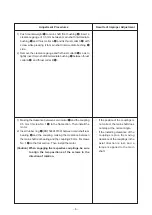
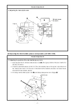
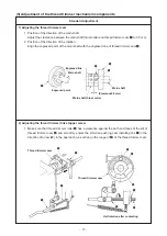
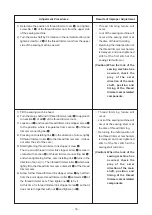
1) Push counterweight
1
to main shaft front bushing
2
, insert a
clearance gauge of 0.5 mm between main shaft intermediate
bushing
3
and thrust collar A
4
and fix thrust collar A
4
with
screw while pressing it to main shaft intermediate bushing
3
side.
2) Remove the clearance gauge and fix thrust collar B
5
so as to
lightly insert main shaft intermediate bushing
3
between thrust
collar A
4
and thrust collar B
5
.
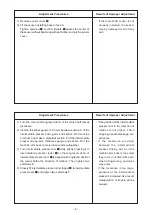
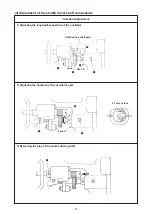
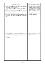
1) Making the clearance between servo motor
1
and the coupling
0.5 mm, fit screw No. 1
4
to the flat section. Then install the
motor.
2) Insert rubber ring
3
(RO1524240100) between main shaft rear
bearing
2
and the coupling. making the clearance between
the main shaft rear bearing and the coupling 2.5 mm, fit screws
No. 1
4
to the flat section. Then install the motor.
(Caution) When engaging the respective couplings, be sure
to align the two positions of the screws in the
direction of rotation.
™
If the position of the couplings is
not correct, the main shaft does
not stop at the normal angle.
™
If the installing clearance of the
couplings is plus, the moving
clearance of the couplings in the
axial direction is lost, and a
torque is applied to the main
shaft.


