


−
95
−
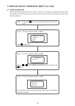
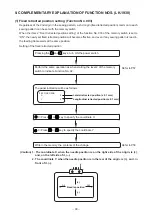
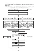
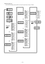
[Setting flow chart when using the bank function]
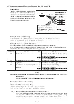
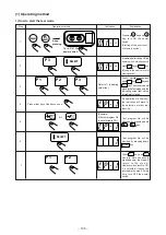
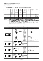
[Panel indication after setting the bank function]
After setting the memory switch, when the machine is started under the bank mode, the panel indication
will be as follows :
By this panel indication, the bank function is
effective and the bank mode is actuated.
[Explanation of panel indication under the bank mode]
According to the contents of the setting of the
item 3 of Function No. 21 of the memory
switch, following indications are given :
When “EXT” is set : EXT
When “PANEL” is set : PANEL
When “ROT” is set : ROT
No : 000
BNK-BLK
XS : 000
EXT
YS : 000
BC : 000
PC : 0000
No : 000
BNK-BLK
XS : 000
EXT
YS : 000
BC : 000
PC : 0000
Flow chart until the bank function is set is as shown in
the figure left.
Start the memory switch
Change the contents of function No.
Write-in of the changed contents
After completing the write-in, turn OFF the power
Bank mode starts by starting under the normal mode.