background image


Section 2  Basic Operations and Mode Screen 

2-20 


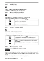
REL, GND, or SEA is added to the end of the display names of TT1 and TT2 buttons depending on 
the radar motion mode or stabilisation mode (e.g. TT1-GND). 


Text 

Motion mode 

Stabilisation mode 

REL 

Relative motion display (RM) 

— 

GND 

True motion display (TM) 

Speed over ground 

SEA 

True motion display (TM) 

Speed through the water 

To use a TTM sentence for the TT symbol display, an OSD sentence must be received from the 

RADAR. 


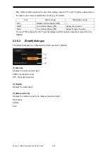
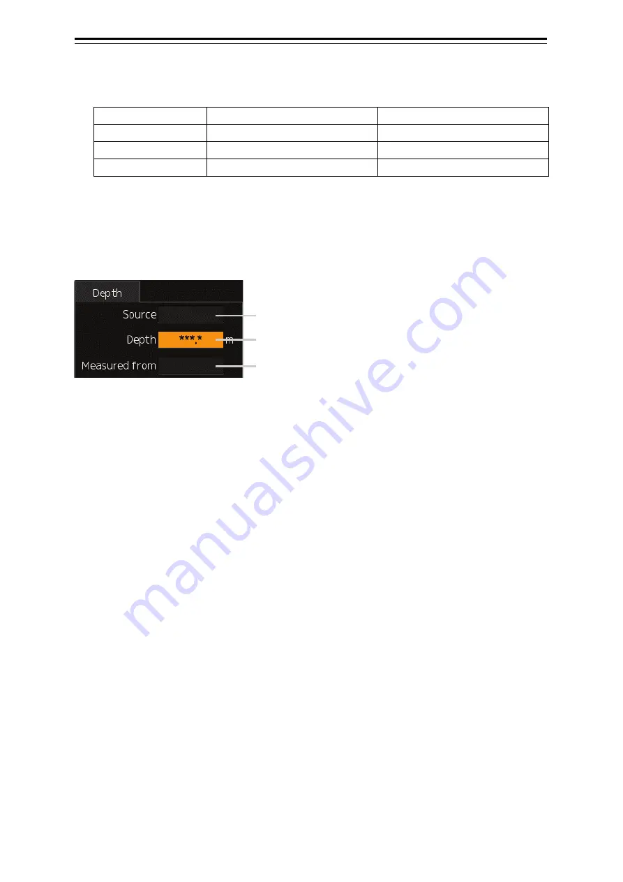
2.2.8.2  [Depth] dialogue 

The [Depth] dialogue box is displayed if a depth sounder is installed. 


(1) [Source] 

Displays the depth sounder used. 
FWD: Front depth sounder 
AFT:  Rear depth sounder 
 

(2) [Depth] 

Displays the water depth. 
 

(3) [Measured from] 

Displays the reference position to measure the water depth. 
Transducer 
Surface 
Keel 


(1) 

(2) 

(3) 

Summary of Contents for JMR-5400 Series

Page 1: ...ER Not use the asbestos For further information contact URL Head office http www jrc co jp eng Marine Service Department 1 7 32 Tatsumi Koto ku Tokyo 135 0053 Japan tmsc jrc co jp 81 50 3786 9201 e mail One call JMR 5400 SERIES JMR 5400 SERIES INSTRUCTION INSTRUCTION MANUAL MANUAL ...

Page 2: ......

Page 3: ...this manual when experiencing operation difficulties z This instruction manual illustrates only plotter operations For radar operations refer to marine radar equipment instruction manuals z The LCD of this equipment uses thin film transistors TFT If some pixels on the screen are not clear the colour is different or the screen is brighter than usual it is not because of defect instead it is because...

Page 4: ...arts are no longer charged Extra protection is ensured by wearing dry cotton gloves at this time Another important precaution to observe is to keep one hand in your pocket at a time instead of using both hands at the same time It is also important to select a secure footing to work on as the secondary effects of electrical shock hazards can be more serious In the event of electrical shocks disinfe...

Page 5: ... Lay the patient on the back loosening the necktie clothes belts and so on 5 a Feel the patient s pulse b Check the heartbeat by bringing your ear close to the patient s heart c Check for respiration by bringing your face or the back of your hand to the patient s face d Check the size of patient s pupils 6 Opening the patient s mouth remove artificial teeth cigarettes chewing gum etc if any With t...

Page 6: ...e a deep breath and blow into the nostril through the pipe with the other nostril and the mouth completely closed 6 The patient may stand up abruptly upon recovering consciousness Keep the patient lying calmly giving him or her coffee tea or any other hot drink but not alcoholic drink to keep him or her warm Mouth to mouth artificial respiration with the patient s head lifted 1 1 Lift the back par...

Page 7: ...are hesitant about giving mouth to mouth resuscitation or preparing the mouthpiece for rescue breathing takes too long omit rescue breathing and proceed to the next step Open the airway Check for breathing Arrival of an AED Turn on the power Use the AED by following its voice prompts Fitting of the electrode pads etc Automatic electrocardiogram analysis Do not touch the injured or ill person Elect...

Page 8: ...Ask for help loudly Ask somebody to make an emergency call and bring an AED Somebody has collapsed Please help Please call an ambulance Please bring an AED If there is nobody to help call an ambulance yourself 5 Open the airway a Touch the forehead with one hand Lift the chin with the two fingers of the middle finger and forefinger of the other hand and push down on the forehead as you lift the ja...

Page 9: ... the mouthpiece for rescue breathing takes too long omit rescue breathing and perform chest compressions c When performing rescue breathing it is recommended to use a mouthpiece for rescue breathing and other protective devices to prevent infections d While maintaining an open airway pinch the person s nose shut with your thumb and forefinger of the hand used to push down the forehead e Open your ...

Page 10: ... over to the emergency services b When the injured or ill person has started moaning or breathing normally lay him her on his her side in a recovery position and wait for the arrival of emergency services 10 Arrival and preparation of an AED a Place the AED at an easy to use position If there are multiple first aiders continue CPR until the AED becomes ready b Turn on the power to the AED unit Dep...

Page 11: ...e the heart rhythm 13 Electric shock defibrillation a If the AED determines that electric shock is needed the voice prompt saying Shock is needed is issued and charging starts automatically b When charging is completed the voice prompt saying Press the shock button is issued and the shock button flashes c The first aider must get away from the injured or ill person make sure that no one is touchin...

Page 12: ... When the injured or ill person has been handed over to the emergency services b When the injured or ill person has started moaning or breathing normally lay him her on his her side in a recovery position and wait for the arrival of emergency services ...

Page 13: ...ment is not operated correctly CAUTION This indication is shown where any person is supposed to be injured or any property damage is supposed to occur if this indication is neglected and this equipment is not operated correctly Examples of Pictorial Indication Electric Shock The mark represents CAUTION including DANGER and WARNING Detailed contents of CAUTION Electric Shock in the example on the l...

Page 14: ...tion inside will cause an electric shock Do not attempt to disassemble or tamper with this equipment Otherwise a fire an electric shock or a malfunction may occur When conducting maintenance make sure to turn the main power off Failure may result in electric shock Turn off all the main powers before cleaning the equipment Make sure to turn it off since voltage is still outputted from the rectifier...

Page 15: ...flash memory while the access lamp in USB flash drive is flashing Data may be damaged when the USB flash memory is inserted or removed while accessing it and it may cause a breakdown Confirm computer virus does not exist in external storage media beforehand when reading and writing of the file by using external storage media Influences other equipment when the display unit is infected with the vir...

Page 16: ...erence target function is to be used if the own ship s speed cannot be displayed normally due to trouble such as a speed sensor malfunction Do not use the reference target function except in emergencies Do not set as a reference target a large radar echo such as a land target The vectors of the speed and other tracking targets will not be displayed correctly and may cause an accident Do not set as...

Page 17: ...Do not place any object on the operation panel In particular if a hot object is placed on the operation panel it can cause deformation of the surface of the operation panel Do not apply any undue shock on the operation panel trackball and dials Otherwise a malfunction may result Make sure that the main power is turned off before inspection or replacement of parts Otherwise an electric shock a fire...

Page 18: ...relative speed CPA or TCPA are referenced typically the conning position of the bridge CORREL CORRELation CPA TCPA Distance to the Closest Point of Approach Time to the Closest Point of Approach CTW Course Through Water The direction of the ship s movement through the water DIST Distance DNV Det Norske Veritas DRIFT The current velocity for manual correction or the current speed on the horizontal ...

Page 19: ...ced past position marks of a tracked or AIS target and the own ship POSN POSitioN PRF Pulse Repetition Frequency The number of radar pulses transmitted each second PROC PROCess Radar signal processing function Q0N A type of radio wave with intra pulse frequency modulation It is used for solid state pulse compression radars RL Rhumb Line RR Range Rings Relative vector A predicted movement of a targ...

Page 20: ...cked target and a AIS target which are decided as the same Chirp A type of transmission waveform with intra pulse frequency modulation used by solid state radars Its radio wave type is classified as Q0N Clutter Unwanted reflections on a radar screen from sea surface rain or snow Display Screen displayed on the LCD Frequency deviation range The range of variation of the Q0N frequency used for trans...

Page 21: ...s a large target such as a large ship in the vicinity Reference target A fixed target specified to calculate the speed over the ground Rubber band Border that indicates the selected range Scale The display scale Sea state The average height of the wave expressed by dividing into several classes Sleeping AIS target A target indicating the presence and orientation of a vessel equipped with AIS Spot ...

Page 22: ...n Example Display the context menu by clicking the right mouse button Button notations The buttons and dialogue boxes on the screen are expressed as follows Button type Notation Button with button name indicated Example AUTO automatic button Button with an indication other than the button name such as an icon Shown as follows Example Day Night button Menu notations A series menus are expressed as ...

Page 23: ...e Information Monitoring Window 2 24 2 4 1 Opening the information monitoring window 2 24 2 4 2 Opening the information monitoring window from a dialogue other than the Page Selection dialogue 2 27 2 5 Managing Files on the File Manager Dialogue 2 28 2 5 1 Managing the files 2 28 2 5 2 Loading saving the destination route file 2 30 Section 3 Operations on the Chart Screen 3 1 3 1 Displaying the Ch...

Page 24: ... New Destination Route 4 6 4 4 1 Registering a new proposed destination 4 6 4 4 2 Creating a new destination route 4 7 4 5 Editing Proposed Destinations 4 11 4 5 1 Edit on the Destination List dialogue 4 11 4 6 Editing the Destination Route 4 14 4 6 1 Edit on the Route Destination dialogue 4 14 4 6 2 Edit on the Route List dialogue 4 15 4 7 Creating a Temporal Route 4 16 4 8 Creating a GoTo Route ...

Page 25: ...ng 6 12 6 4 2 Configuring the scale and range 6 13 6 4 3 Configuring the chart operation 6 16 6 4 4 Configuring the current position display 6 17 6 4 5 Setting the colour and brightness 6 19 6 4 6 Setting the key assignment 6 20 6 4 7 Configuring user preferences 6 22 Section 7 Specifications 7 1 7 1 Plotter Functions 7 1 Appendix A Alert List A 1 A 1 Alarms A 2 A 2 Warnings A 3 A 3 Cautions A 9 A...

Page 26: ... 2 5 GPS Buoy B 46 B 2 6 NAVTEX B 46 B 2 7 User Map B 47 B 2 8 Monitoring dargging anchor B 49 B 3 List of Terminologies Units and Abbreviations B 50 B 4 List of Navigation related Symbols B 58 B 4 1 Navigation monitoring related B 58 B 5 List of Icons Icon Buttons B 59 B 6 Cursor types B 64 Software Licence Agreement B 66 Font Licence Agreement B 67 IPA Font Licence Agreement v1 0 B 68 ...

Page 27: ... in plotter mode The following shows an example of the mode screen in plotter mode and relevant sections to be referenced for each part of the screen Memo This document describes operations in plotter mode See also the Instruction Manual of the ship radar equipment See 2 2 3 Ship information See 2 2 7 Chart information area See 2 2 1 Menu button See 2 2 2 Key assignment display area See 2 2 4 Righ...

Page 28: ...ing my Ports Chart Off Centre by Entering Position 6 1 2 Displaying the chart by inputting the position Tools EBL VRM 3 3 Displaying the EBL VRM Button Tools Cursor Readout 3 4 Displaying the Cursor Readout Dialogue Tools File Manager 2 5 Managing Files on the File Manager Dialogue View Own Ship 6 2 1 Configuring the ship symbol display View Own Track 6 2 2 Configuring own track display View WPT R...

Page 29: ...mode the following functions can be selected No Function name Functional overview 1 Vector Time Select a vector length 2 C UP Angle Change the course up angle 3 Own Track Colour Select an own track colour 4 Mark Line Colour User map colour 5 Manual Tune Adjustment of manual tuning 6 Display Brightness Adjust the brightness of the display unit 7 Panel Brightness Adjust the brightness of the operati...

Page 30: ...en the 1 axis log is used the velocity component in the forward direction can be detected but the velocity component in the lateral direction cannot be detected Therefore the leeway effect off course movement due to wind cannot be detected When the 2 axis ground log is used the accuracy may degrade in a shoal The velocity may not be detected in the abyssal zone When the GPS is used the COG precisi...

Page 31: ... Selection Status dialogue Sensor name Sensor source HDG Manual Gyro Gyro 1 1 4 Gyro 2 1 4 MAG MAG Compass 4 G C GPS Compass STW Manual Log 5 Log 1 2 5 Log 2 2 5 COG Log 5 Log 1 2 5 Log 2 2 5 GPSx 3 SOG 1 Only with two gyrocompasses 2 Only with two logs 3 x indicates a device number if more than one GPS is used 4 If a gyrocompass system with the automatic switching feature is used the sensor sourc...

Page 32: ...GPS is used 3 The Geodetic Positioning System of POSN is displayed 4 The positioning precision is displayed If the positioning precision is differential positioning DGPS is displayed If the positioning is GPS alone positioning nothing is displayed 5 CCRP position The CCRP position from the primary sensor is displayed 6 Badge display area Offset This badge is displayed when offset is set for own sh...

Page 33: ... In case someone falls over board the ship position when this button is clicked on is marked so as not lose the fallover position For details see the Instruction Manual of the ship radar equipment Message notification button Click on it to display the latest notification messages received regarding AIS MSG Tray and NAVTEX For details of the message dialogue of each received information see the Ins...

Page 34: ...ol bar Some buttons are hidden in normal cases Change the button display by clicking on the disclosure button Displayed in normal cases Hidden in normal cases See the next page for the name and description of each button Click on the disclosure button to show the buttons that are hidden in normal cases Disclosure button ...

Page 35: ...the AUTO mode For details of the cursor mode see the Instruction Manual of the ship radar equipment Undo cancel button Cancels the previous operation Operations in the following mode can be cancelled User map creation mode Own Track Target Track Data Off button Click on it to display only the main information and hide other information The following information will be displayed RADAR Echo trail C...

Page 36: ...n Manual of the ship radar equipment HL Off button Click on it to hide the heading flash For details of the heading flash see the Instruction Manual of the ship radar equipment Eraser tool button Click on it to activate the user map deletion mode Continuous deletion is possible Def button Resets the user preferences to the factory default settings It works in the same way as the Initialise the dis...

Page 37: ... sections buttons and tools 2 2 7 1 Scale range combo box The current scale or range is displayed Scale Range Select a scale or range from this combo box Click on the scale range combo box to display the scale range selection list Select a scale or range value from the list to display the chart with the selected scale or range Scale value Range value ...

Page 38: ...d and other objects are fixed on the screen and only the ship moves The chart automatically shifts when the ship reaches the predefined end of the screen so that the ship is always displayed in the upper part of the screen RM Relative Motion Mode The ship is fixed in the centre of the screen and the ground and other objects move relatively Free Free mode The chart can be moved freely regardless of...

Page 39: ...ed with the ship s heading direction upward It cannot be selected in TM true motion or Fee mode C UP Course Up display The ship s heading direction HDG is fixed on top in course up mode C UP Angle Setting Course Up display course angle setting Select this to display the C UP Angle Setting dialogue The course angle heading angle set on the dialogue is fixed on top of the screen Enter the angle in t...

Page 40: ...ard click on this button and remove the card after the icon is set to a removal enabled status The statuses of the icon are shown in the table below Icon Status Enabled When this icon is clicked on the removal of the card is requested Disabled The removal of the card is disabled while card removal is being requested Removal enabled The card removal request is successful and the SD card can be remo...

Page 41: ...ack colour is displayed When the Track is enclosed with blue borders the multi function knob is assigned the colour change function Click on the colour icon to display the Plot Colour dialogue on which you can select a colour from the following White Grey Amber Magenta Blue Cyan Green Yellow Orange Dark Red ...

Page 42: ...idden in see clutter Sea clutter restriction is prioritized while the sensitivity of moving objects degrades Storm Used in storms where the rain and snow clutter or sea clutter is significant Sea rain and snow clutter restriction is prioritized while the sensitivity degrades a little Calm Used when the rain and snow clutter or sea clutter is not significant Rain Used when the sea clutter is not si...

Page 43: ... the cursor to the upper left corner A of the target range then move the cursor to the bottom right corner B and then click on the button The selected area is enlarged to full screen size The zoom cursor changes back to the cross hair cursor In button Click on it to zoom in the chart Out button Click on it to zoom out the chart Slider Move the slider knob upward to zoom in the chart Move the slide...

Page 44: ...nput range 1 to 120 min 2 Radar overlay button Turns on off the radar overlay display Click on it to turn on off the overlay If the radar is not installed nothing is displayed ON OFF If multiple radars are installed select radar system to use from the combo box Tabs Click on each tab to display relevant information Watch dialogue See 2 2 8 1 Watch dialogue Depth dialogue See 2 2 8 2 Depth dialogue...

Page 45: ... OFF b AIS filter display button When AIS is ON Filter is displayed When the AIS filter is ON Filter is enclosed with blue borders 4 TT1 TT2 TT1 TT2 function button a TT1 TT1 function button Turns on off TT1 Click on it to turn on off the function If TT1 is disabled nothing is displayed ON OFF b TT2 TT2 function button Turns on off TT2 Click on it to turn on off the function If TT2 is disabled not...

Page 46: ...y TM Speed over ground SEA True motion display TM Speed through the water To use a TTM sentence for the TT symbol display an OSD sentence must be received from the RADAR 2 2 8 2 Depth dialogue The Depth dialogue box is displayed if a depth sounder is installed 1 Source Displays the depth sounder used FWD Front depth sounder AFT Rear depth sounder 2 Depth Displays the water depth 3 Measured from Di...

Page 47: ...scription True motion display Draws the absolute trails of other ships irrelevant to the own ship This mode is useful to determine the courses and speeds of other ships No motion trails for fixed objects such as the land is drawn Relative motion display Draws the trails of other ships relative to the own ship This mode is useful to determine whether other ships are coming closer to the own ship Mo...

Page 48: ... the trail length The following trail lengths can be selected depending on the radar trail length set in the radar mode Short mode Off 15 sec 30 sec 1 min 3 min 6 min 10 min 15 min 30 min 60 min Long mode Off 30 min 1 hour 2 to 24 hours units of hours Drawing of trails starts when transmission starts If the elapsed time after the transmission started is short the display may not satisfy the specif...

Page 49: ...ow see the Instruction Manual of the ship radar equipment The Common Information window consists of the Information Monitoring window and the Information Reference window In plotter mode the Information Monitoring window is displayed at bottom right by default but this floating window can be moved freely For details of how to operate the Information Monitoring window see 2 4 Operating the Informat...

Page 50: ...scribes operations and edit of the Information Monitoring window in plotter mode 2 4 1 Opening the information monitoring window 1 Click on the page switching button on the initial window Initially the content is empty Click on the page switching button to display the Page Selection dialogue Page switching button ...

Page 51: ...2 25 Section 2 Basic Operations and Mode Screen 2 2 Clicking on the monitoring information you want to show opens the relevant window Click ...

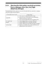
Page 52: ... button on each window to go back to the Page Selection dialogue Displaying items in a separate window 1 Select check boxes for items you want to display in a separate window 2 Click on New Window separate window button The items are displayed in a separate window Memo Windows already opened cannot be opened in a separate window Click ...

Page 53: ...g window Display method Target INFO 1 Click on the TT symbol Cursor AUTO mode 2 Right click on the TT AIS symbol and select Readout information from the context menu 3 Click on the AIS Activated Target Cursor AUTO mode TT1 List TT2 List 1 From TT AIS of the menu select the TT AIS list AIS List 1 From TT AIS of the menu select the TT AIS list AIS Detail INFO 1 Select an AIS target from the AIS List...

Page 54: ... Manager enables you to copy delete files between the SSD of the equipment and external media Memo The following describes operations on the File Manager dialogue in plotter mode For details of the operations on the File Manager dialogue in radar mode see the Instruction Manual of the ship radar equipment The following table lists the items displayed on the File Management tab Item Description Fil...

Page 55: ...on route plotter mode User Map uchr User map Own Track otr Own Track Target Track ttr Other ships routes including GPS buoy routes Screen Shot AUTO PNG file Automatically generated screen shots Screen Shot User PNG file Manually generated screen shots Preferences ini Personal settings 3 Select check boxes of desired files 4 Select a save destination drive from the Drive combo box and select a save...

Page 56: ... and Destinations It is displayed when Plotter Route is selected as the file type The currently stored destination route and proposed destination are saved Delete Current Route and Destinations It is displayed when Plotter Route is selected as the file type The currently stored destination route and proposed destination are deleted File list Name Displays the file name 2 5 2 1 Loading the destinat...

Page 57: ...tton A confirmation dialogue is displayed 4 Click on the OK button The stored destination route data is deleted from the screen 2 5 2 3 Saving the destination route file 1 Click on the File Load Save tab 2 Select Plotter Route from the File Type combo box 3 Click on the Save Current Route and Destinations button A confirmation dialogue is displayed 4 Enter the file name in the input field and clic...

Page 58: ...Section 2 Basic Operations and Mode Screen 2 32 ...

Page 59: ...t View dialogue to configure the multi view display Memo For details of buttons other than the Multi View Mode button of the Chart View dialogue see the Instruction Manual of the ship radar equipment 3 1 1 Displaying the multi view screen 1 Click on the Multi View Mode button The Multi View Mode dialogue is displayed Select a display mode from Multi View Mode on the Multi View Mode dialogue Displa...

Page 60: ...n View1 1 Click on the Select Area from View1 for View2 button on the Multi View Mode dialogue The button is highlighted 2 Move the cursor to View1 The cursor changes to the range selection cursor 3 Move the cursor to the start point of the range and click then drag the cursor to determine the range to display in View2 4 Click The selected range is displayed in View2 The Select Area from View1 for...

Page 61: ...tion via Dropped EBL VRM Make EBL1 VRM1 or Make EBL2 VRM2 Dropped EBL VRM Make EBL1 or Make EBL2 3 2 2 Operation via Dropped EBL VRM Make EBL1 or Make EBL2 Dropped EBL VRM Make VRM1 or Make VRM2 3 2 3 Operation via Dropped EBL VRM Make VRM1 or Make VRM2 Dropped EBL VRM Move base point of EBL1 VRM1 or Move base point of EBL2 VRM2 3 2 4 Operation via Dropped EBL VRM Move base point of EBL1 VRM1 or M...

Page 62: ...measurement base point is displayed on the cursor 3 Move the cursor to any position and click The measurement base point will be fixed 4 Move the cursor to adjust the direction and distance and click at any position The ELB1 direction and VRM1 distance will be fixed 3 2 2 Operation via Dropped EBL VRM Make EBL1 or Make EBL2 Operations are common in EBL1 and EBL2 The following description is based ...

Page 63: ...base point of EBL1 VRM1 and Move base point of EBL2 VRM2 The following description is based on Move base point of EBL1 VRM1 1 Right click on the chart to display the context menu 2 Select Dropped EBL VRM Move base point of EBL1 VRM1 from the context menu EBL1 and VRM1 are displayed and the measurement base point is displayed on the cursor 3 Move the cursor to any position and click The EBL VRM mea...

Page 64: ...easurement base point is displayed on the ship 3 Move the cursor to any position and click The ELB1 direction will be fixed 3 2 7 Operation via CCRP EBL VRM Make VRM1 or Make VRM2 Operations are common in VRM1 and VRM2 The following description is based on VRM1 1 Right click on the chart to display the context menu 2 Select CCRP EBL VRM Make VRM1 from the context menu VRM1 is displayed and the mea...

Page 65: ...L VRM readout dialogue The following describes how to display the EBL VRM readout dialogue Procedure Use the following operation to display the EBL VRM readout dialogue Menu button Tools EBL VRM Memo In radar mode the EBL VRM button is always displayed Operation of the EBL VRM button is the same in both the plotter and radar modes For details see the Instruction Manual of the ship radar equipment ...

Page 66: ... in plotter mode 1 Base point setting button The base point for the cursor direction distance display can be set to any point For details see 3 4 1 Setting the base point for CURS INFO 2 TTG and ETA display Displays TTG total time to go and ETA estimated time of arrival from the ship to the cursor point 3 Latitude and longitude of the cursor point Displays the latitude and longitude of the cursor ...

Page 67: ...f the base point for CURS INFO Up to 20 base points can be configured 1 Click on the base point setting button The menu is displayed 2 Click on Edit Ref Mark The Edit Reference Mark dialogue is displayed 3 Click on the LAT input field of line 1 4 Enter the latitude using the software keyboard When the latitude is entered the longitude can be entered 5 Enter the longitude using the software keyboar...

Page 68: ...ogue click on the reference mark number to move to and click on the Jump button The chart is centred on the selected base point 3 4 1 3 Deleting the configured base point On the Edit Reference Mark dialogue click on the reference mark number to delete and click on the Delete button The selected base point will be deleted ...

Page 69: ...reation The flow of destination route creation is as follows Register multiple proposed destinations See 4 4 1 Registering a new proposed destination Connecting proposed destinations by legs See 4 4 2 Creating a new destination route Example destination route In this example proposed destinations 001 to 004 are registered Proposed destinations 004 003 and 001 are connected by legs to create the de...

Page 70: ...g Configure the alert ON OFF setting and the conditions for issuing the alerts entry and leaving alert 6 3 1 Configuring the alerts for the destination route Destination arrival leaving alert setting Configure the arrival circle turn on off the alert on the arrival circle and configure the conditions for issuing alerts the arrival circle entry and leaving alerts 6 3 1 Configuring the alerts for th...

Page 71: ...g Setting value WPT Number Comment Turns on off the proposed destination number and comment display Check it to enable the setting Enabled Checked Disabled Unchecked Text Size combo box Destination Number Comment Switch the text size between Standard and Small for the destination number and comment Standard Small Route Numb Turns on off the route number display Check it to enable the setting Enabl...

Page 72: ...t sections 1 Title Bar The title Route Destination is displayed on the dialogue Enter a number in the No field The contents of the dialogue change depending on whether the number is a proposed destination number or route number or new or existing number 2 No input field Enter the proposed destination number or route number Then if the start point button is pressed the input number is deemed as a r...

Page 73: ... The functions of the above buttons of the Route Destination dialogue are assigned to the keys of the operating unit as described in the following table This key assignment takes priority only while the Route Destination dialogue is displayed Button on the dialogue Standard operating unit Advanced operating unit Enter button Left click Left click Input key Clear button Right click Right click CLR ...

Page 74: ...y on the operating dialogue 1 Enter the number for the new proposed destination in the No field Example When 999 is entered The title bar of the Route Destination dialogue changes to Destination 999 New The cursor on the chart changes to the Mark cursor 2 Move the Mark cursor to the point on which you want to add a proposed destination and click on it The proposed destination is created on that po...

Page 75: ... advanced operating unit you can use the input key instead of left clicking The proposed destination specified becomes WPT 4 Enter the next proposed destination number of the route in the No field and then click on the Enter button When you are using the operating unit enter the number and left click on anywhere except the dialogue buttons When you are using the advanced operating unit you can use...

Page 76: ...e Click on this button to open the Select Route dialogue The Select Route dialogue lists the route numbers and the comments created Click on a route you want to edit and click on the Open button to display the route on the Route List dialogue 3 Comment input field Enter the comment for the route Up to 32 characters can be entered is displayed at the end if the text is longer than the field width I...

Page 77: ...utton The entire route being edited is displayed on the chart 7 Destination List dialogue button Click on this button to open the Destination List dialogue Proposed destinations registered and their positions latitude and longitude are displayed on the Destination List dialogue Routes can be edited while referring to the Destination List dialogue When both the Route List dialogue and Destination L...

Page 78: ...ed destination number in line 2 of the Route List The proposed destination specified at step 1 and the proposed destination specified at step 2 are connected by a leg 4 Repeat step 2 to connect other proposed destinations by legs to create the route 5 Click on the button to close the Route List dialogue The created route is determined as a new destination route Memo If the number of proposed desti...

Page 79: ...logue Item Function and operation Input range Page feed buttons Used to switch between pages when the dialogue has multiple pages Returns to the first page Returns to the previous page Goes to the next page Goes to the last page Page field Enter the number of pages to display 1 to 100 Route List dialogue Opens the Route List dialogue Jump button Displays the selected proposed destination in the ce...

Page 80: ...LAT field 2 Enter the latitude using the software keyboard When the latitude is entered the longitude can be entered 3 Enter the longitude using the software keyboard When the input latitude and longitude are valid this new position is set for the destination 4 Click on the button to close the Destination List dialogue 4 5 1 3 Editing the comment of a proposed destination Open the Destination List...

Page 81: ...estination Open the Destination List dialogue and operate it as follows 1 Click on the number for the destination you want to delete 2 Click on the Delete button The selected destination will be deleted 3 Click on the button to close the Destination List dialogue ...

Page 82: ...te Destination dialogue see 4 3 Opening the Route Destination Dialogue 4 6 1 2 Moving to a proposed destination 1 Enter a destination number in the No field to display the destination Example When 1 is entered The title bar of the Route Destination dialogue changes to Destination 1 2 Click on the Off Centre button The proposed destination specified at step 1 is displayed in the centre of the chart...

Page 83: ...ions of the Route List dialogue see 4 4 2 2 Creating a route on the Route List dialogue 4 6 2 2 Adding editing a comment to the destination route Open the Route List dialogue and operate it as follows 1 In the Route No field enter the number for the destination route you want to edit Click on the Select Route dialogue display button click to select a route to edit on the Select Route dialogue and ...

Page 84: ... turned off For details see 5 2 2 Configuring Settings Route from the menu Use the procedure to create a temporal route 1 Display the first WPT point in the chart 2 Press the start point key WPT is created on the point where the key is pressed and the cursor changes to the Mark cursor 3 Hover the Mark cursor on the next WPT position and press the start point key These two WPT are connected by legs...

Page 85: ...oral routes GoTo routes are created via key operations on the operating unit without opening the Route Destination dialogue Use the procedure to create a GoTo route 1 Hover the cursor on the end point of the GoTo route 2 Press the end point key The GoTo route connecting the ship and another point is determined and route monitoring starts automatically Memo For details of route monitoring using a G...

Page 86: ...Section 4 Route Planning 4 18 ...

Page 87: ...ng on the Route Monitoring dialogue Use the following operation to open the Route Monitoring dialogue Menu button Route Monitoring 1 Select a destination route to be monitored Using the Route No field Enter the number for the destination route to be monitored Valid values are 1 to 999 Selecting from the route file list 1 Click on the Select Route dialogue display button 2 Select a destination rout...

Page 88: ...ton Route monitoring starts Memo If another route is being monitored that route will be unloaded The Route Destination dialogue closes and the Voyage Information dialogue opens when route monitoring starts For details of the Voyage Information dialogue see 5 3 Voyage Information Dialogue 5 1 1 3 Monitoring a temporal GoTo route Route monitoring starts and the Voyage Information dialogue opens when...

Page 89: ... the Voyage Information dialogue 2 Click on the Unload button Monitoring of the currently selected route will end 5 1 2 2 When route monitoring is started from the Route Destination dialogue When route monitoring is started from the Route Destination dialogue first Use the following operation to open the Route Monitoring dialogue Menu Route Monitoring 1 Ensure that the number for the route being m...

Page 90: ...alogue with the Route dialogue displayed in the Edit pane On this dialogue configure the conditions the XTL width radius of the arrival circle etc for issuing alerts for the destination route WPT Vector check box Check it to enable the WPT direction vector display Enabled Checked Disabled Unchecked Base Point combo box WPT Vector The WPT direction vector is a line connecting the selected base poin...

Page 91: ...n NMEA is selected all the other setting items of this dialogue are disabled Plotter NMEA WPT Switching Mode combo box Set whether To WPT is switched automatically or manually AUTO To WPT is switched automatically Manual To WPT is switched manually With AUTO selected when the ship enters the arrival circle of the To WPT the next WPT will be the To WPT AUTO works only if Alert Type is set to Arriva...

Page 92: ...play content and operation Display input range Route filed It is displayed only when the dialogue is extended The number for the route being monitored is displayed 1 to 999 WPT filed Select a number for the destination for which route monitoring information is displayed 1 to 1020 To WPT field It is displayed only when the dialogue is extended The To WPT number is displayed 1 to 1020 LAT LON field ...

Page 93: ...ring The route entry alert is selected and an alert is occurring The route leaving alert is not selected The route leaving alert is selected but no alert is occurring The route leaving alert is selected and an alert is occurring TTG field Displays the time required to arrive at the destination selected from the WPT combo box 0 0 to 9999h59m59s ETA field Displays the estimated time of arrival at th...

Page 94: ...To WPT The reversed state is retained even after the power supply is turned off The reversed state is cancelled when another route monitoring is started Use the following operation to open the Route Destination dialogue Menu button Route Planning Set Route Destination 1 Click on Reverse button The route being monitored is reversed Memo The reverse button is disabled if no route is being monitored ...

Page 95: ...ng is started from the Route Destination dialogue first Use the following operation to open the Route Monitoring dialogue Menu button Route Monitoring 1 Ensure that the number for the route being monitored is displayed in the Route No field 2 Select a destination to be used as To WPT from the To WPT combo box The changed To WPT number will be displayed also in the To WPT field of the Voyage Inform...

Page 96: ...Section 5 Route monitoring 5 10 ...

Page 97: ...ist dialogue Setting item Description Setting value My Port List field Enter a port name to register Save button Clicking on this button registers the coordinates latitude longitude of the centre and the display scale of the chart in My Port List 6 1 1 2 Centring the chart on the coordinates of the port Procedure Use the following operation to display the My Port List dialogue Menu button Chart My...

Page 98: ...ion to display the chart on the desired position Procedure Use the following operation to display the Off Centre by Entering Position dialogue Menu button Chart Off Centre by Entering Position The following table describes operations of the Off Centre by Entering Position dialogue Setting item Description Setting value Jump to the following position button Clicking on this button centres the chart...

Page 99: ...ialogue in the Edit pane of the View dialogue Menu button View Own Ship The following table lists the setting items available in plotter mode Setting item Description Setting value Heading and Beam Line Selecting this enables to display heading lines and beam lines Enable Check Disable Uncheck Memo For details of setting items of the Own Ship dialogue see the Instruction Manual of the ship radar e...

Page 100: ...le Enable Check Disable Uncheck Show Values Vector on Track check box Check it to display the water depth water temperature and the current vector Select Depth Temperature or Current from the Show Values Vector on Track combo box Enable Check Disable Uncheck Show Values Vector on Track combo box Select Depth Temperature or Current to display it next the track Depth Temperature Current Current Vect...

Page 101: ...h Temperature Plot Colour combo box Select a colour of own track White Grey Amber Magenta Blue Cyan Green Yellow Orange Dark Red Plot Interval combo box own track plot Select a plot interval Off 3 s 5 s 10 s 30 s 1 min 3 min 5 min 10 min 30 min 60 min 1 NM 3 NM 5 NM 10 NM 0 1 NM 0 2 NM 0 3 NM 0 5 NM Time Label check box Check it to enable the time label interval display Enable Check Disable Unchec...

Page 102: ...ack blue cyan boundary minimum depth value Depth field 1 1 to Depth field 3 1 m Depth field 3 Enter the own track cyan green boundary minimum depth value Depth field 2 1 to Depth field 4 1 m Depth field 4 Enter the own track green yellow boundary minimum depth value Depth field 3 1 to Depth field 5 1 m Depth field 5 Enter the own track yellow orange boundary minimum depth value Depth field 4 1 to ...

Page 103: ...ue Temperature field 1 1 to Temperature field 3 1 C Temperature field 3 Enter the own track cyan green boundary minimum temperature value Temperature field 2 1 to Temperature field 4 1 C Temperature field 4 Enter the own track green yellow boundary minimum temperature value Temperature field 3 1 to Temperature field 5 1 C Temperature field 5 Enter the own track yellow orange boundary minimum tempe...

Page 104: ...dialogue Menu button View Target The following table lists the setting items available in plotter mode Setting item Description Setting value TT1 Symbol TT2 Symbol check boxes and combo boxes Check the check box to enable TT1 TT2 symbol display Select a TT symbol to be used from the combo box TT1 Symbol Indicates the tracking target received from Radar 1 The TT target ID will be displayed in a for...

Page 105: ...ft section of the chart display area Off Cursor Readout Own Ship INFO Voyage INFO Top Right combo box Set the information to be expanded and displayed at the top right section of the chart display area Off Cursor Readout Own Ship INFO Voyage INFO Bottom Left combo box Set the information to be expanded and displayed at the bottom left section of the chart display area Off Cursor Readout Own Ship I...

Page 106: ...nformation Window check box Check it to enable the sub information area Enable Check Disable Uncheck Watch Vector RADAR Target Status check box Check it to enable the Watch dialogue Enable Check Disable Uncheck Depth check box Check it to enable the Depth dialogue Enable Check Disable Uncheck Current check box Check it to enable the Current dialogue Enable Check Disable Uncheck Trails check box Ch...

Page 107: ... Select an alert type if the WPT alarm is ON Arrival An alert is issued when the ship arrives in the circle with the configured radius Break Off An alert is issued when the ship leaves the circle with the configured radius Arrival Break Off Arrival Radius field When the WPT alarm is ON set the radius of the arrival circle of the destination 0 01 to 99 99 NM Route Alert check box Specify whether to...

Page 108: ...the knob or the button next to the slider can switch the mode between auto AUTO and manual MAN 0 to 100 MAN Remove sea clutter manually AUTO Sea clutter is removed automatically Rain Rotate the knob to enter the rain and snow clutter adjustment mode In adjustment mode clicking on the knob or the button next to the slider can switch the mode between auto AUTO and manual MAN 0 to 100 MAN Remove rain...

Page 109: ...utton to add the scale value input in the Scale field to the scale list The scale list is always sorted in ascending order Delete button Click on it to delete scales checked on the scale list located below the button Scales cannot be deleted if all the scales are selected or there is only one scale Def Set button Resets the scales to the default settings On the confirmation dialogue that opens cli...

Page 110: ...scribed below Ranges cannot be deleted if all the ranges are selected or there is only one range Def Set button Resets the ranges to the default settings On the confirmation dialogue that opens click on OK to restore the default For the default scale settings see Default values of scales and ranges Check box Check the check boxes for the ranges you want to delete Click on Delete to delete the sele...

Page 111: ...5 2 1 2 000 0 25 0 30 3 1 4 000 0 500 0 50 4 1 7 500 0 750 0 80 5 1 15 000 1 500 1 20 6 1 30 000 3 000 1 60 7 1 50 000 6 000 2 00 8 1 100 000 12 000 4 00 9 1 200 000 24 000 8 00 10 1 400 000 48 000 16 00 11 1 750 000 96 000 32 00 12 1 1 500 000 64 00 13 1 3 000 000 128 00 14 1 5 000 000 15 1 10 000 000 16 17 18 19 20 ...

Page 112: ...ings dialogue Menu button Settings Chart Setting Item Description of Setting Setting Value Border Range Set up the range for the own ship in order to move the chart When the own ship is sailing in the direction of the arrow in the figure below If the border range you set up is 50 the screen display switches when the own ship reaches a 50 area from an edge of the screen 30 to 80 ...

Page 113: ...CCA LORAN C tab Chain combo box Select GRI for the master station chain For details of master stations see the List of LORAN C master stations TD1 field Set the ID of slave station 1 0 to 99 TD1 Correction field Set the transmission delay time for slave station 1 9 9 to 9 9 μs TD2 field Set the ID of slave station 2 0 to 99 TD2 Correction field Set the transmission delay time for slave station 2 9...

Page 114: ... 9 9 μs LOP2 combo box zone Set the zone of slave station 2 0 to 9 LOP2 combo box lane Set the lane of slave station 2 A to J LOP2 field Set the frequency of slave station 2 00 00 to 99 99 TD2 Correction field Set the transmission delay time for slave station 2 9 9 to 9 9 μs List of LORAN C master stations Master station Remarks Master station Remarks 4990 7980 5930 7990 5970 8000 5980 8290 NORTH ...

Page 115: ...e Page 2 Expand Information combo box Set a colour of the characters displayed for the expanded information Black White 1 Green Yellow Orange Magenta 1 Black when the day night mode is Day 1 Day 2 Day 3 and White in other cases Brightness tab Setting item Description Setting value Page 1 Expand Information combo box Set a brightness of the characters displayed for the expanded information Level1 D...

Page 116: ...me as above Set a User key1 to 10 only if the multi function operation unit is connected Memo For other setting items of the Key Assignment dialogue see the Instruction Manual of the ship radar equipment User Key list The following table shows the functions that can be assigned to user keys Function Description Show Preset Menu Display the pre registered screen By displaying a screen to be registe...

Page 117: ... that was registered by Record Operation TM Reset Execute the TM reset function PRF Fine Tuning Increment by 1 the setting of Settings TXRX PRF Fine Tuning Acquire Perform the same operation as the acquisition key of the multi function operation unit Readout Information Perform the same operation as the numeric key of the multi function operation unit Clear Execute the Clear function for the objec...

Page 118: ...n Deletes the selected setting Default display configurations button Restores the default display configuration To save user preference 1 Click on the Save button A confirmation dialogue is displayed 2 Enter a name and click on the OK button The current user preference is saved Up to 64 characters can be entered An ellipsis is added to the end if the text is longer than the field width To cancel t...

Page 119: ... the OK button The factory default display configuration is restored To cancel the change click on the Cancel button Setting items and default settings of user preference The following table lists the setting items and default settings of user preference with the optional plotter installed Plotter mode Save item Preference to be saved Default setting or value after Default display configurations i...

Page 120: ...F OFF Operational alarms Alert Collision Avoidance AIS Lost Warning AIS Lost Warning AIS Lost Warning detection target setting ON OFF TT Activated AIS VRMs Radar screen Measuring tools EBL VRM button area VRM1 VRM2 Display ON OFF Control right Distance value EBL1 VRM1 measurement base point Empty C D and floating position C is saved with the DC coordinates and D is saved with the coordinates VRM d...

Page 121: ...Link OFF Reference Bearing True Display mode of the radar picture Radar screen Range and mode information Motion mode Direction mode TM N UP TM reset position Stabilisation Sea Ground Radar screen Range and mode information Stabilisation mode combo box GND Off Centring Radar screen Range and mode information Off Centring button Off centring ON OFF state and off centring DC state Off Centring OFF o...

Page 122: ...stance AZ1 function ON OFF OFF AZ1 Start Angle 315 0 AZ1 End Angle 045 0 AZ1 Start Distance 3 00 NM AZ1 End Distance 3 50 NM AZ2 function ON OFF OFF AZ2 Start Angle 135 0 AZ2 End Angle 225 0 AZ2 Start Distance 3 00 NM AZ2 End Distance 3 50 NM Graphical AIS reported target fusion View Target AIS Symbol ON OFF TT Symbol ON OFF AIS Symbol ON OFF ON TT Symbol ON OFF ON Radar and AIS Target fusion Sett...

Page 123: ...e range scale coast line by manual Own track Colours 10 colours Interval of save 3 5 10 30 sec 1 3 5 10 30 60 min or 0 1 0 2 0 3 0 5 1 3 5 10 NM and Off Capacity of own track 1000 000 point User Map Colours Mark Line 10 colours Capacity of mark and line 200 000 point Variety of mark 29 Variety of line Solid line Dotted line and Broken line Waypoint and route Waypoint Waypoint can be set up to 999 ...

Page 124: ...Section 7 Specifications 7 2 ...

Page 125: ...sking sailors to pay immediate attention and take immediate action Alarms Red Before alarm acknowledgement Blinking After alarm acknowledgement Lighting Present repetitive Warnings An alert indicating that the state has changed which although is not immediately dangerous but may become so in the near future if no action is taken Warnings are alerts displayed for preventing possible future hazardou...

Page 126: ...idance function cannot be executed due to a failure or a communication error of sensor or radar antenna CPA TCPA AIS CPA TCPA alarm AIS CPA TCPA TT CPA TCPA alarm TT Cross Track The off track distance from the planned route exceeded the limit Depth below keel The depth below keel is too shallow Dragging anchor The ship has left the dragging anchor monitoring area ...

Page 127: ...l Lost RADAR Proc Unit detected an error in an interrupt signal Terminal Board Communication failed Communication with terminal board cannot be performed via LAN CMP RelaySoftware Communication error There is an error in communication with Companion MPU COG SOG invalid There is a format error or a status error of the SOG COG data COG SOG not plausible There is a range error of SOG COG data COG SOG...

Page 128: ... Communication error There is a communication error with the operation unit 1 OPU1 Keyboard Connection Key encoder circuit was detected an open error in the operation unit 1 OPU2 Communication error There is a communication error with the operation unit 2 OPU2 Keyboard Connection Key encoder circuit was detected an open error in the operation unit 2 Position doubtful The integrity of Position cann...

Page 129: ...as been lost TT Max Target The TT target count has reached the maximum target count TXRX AZI Azimuth signals cannot be recognized in the radar antenna TXRX BP DET ERR The number of BP detection in the radar antenna falls short of the rated value TXRX BZ DET ERR The detection of BZ in the radar antenna cannot be performed TXRX Communication error There is a communication error with radar antenna TX...

Page 130: ...he radar antenna exceeds the rated value TXRX MOT OVV The motor voltage of MOT circuit in the radar antenna exceeds the rated value TXRX MOT Temperature The temperature of MOT circuit in the radar antenna is abnormal TXRX MOT Warning Temperature The temperature of MOT circuit in the radar antenna exceeds the warning value TXRX Option The option equipment in the radar antenna is abnormal TXRX PHI A...

Page 131: ... TXRX Trigger There is possibility that timing reference signals are not normally output from the radar antenna TXRX TX Connection The connection of TX circuit in the radar antenna is abnormal TXRX TX Fan The fan of TX circuit in the radar antenna is abnormal TXRX TX Temperature The temperature of TX circuit in the radar antenna is abnormal VDR Delivery Failed Delivery of captured image for VDR fa...

Page 132: ...n AIS SOG data has not been input or is invalid 029 Not Transmitting Tx malfunction AIS Malfunction at or during transmission 001 Pa current error AIS Error in the current during transmission 054 Pa temp error AIS Abnormal temperature rise during transmission 055 Power supply error AIS Error in power supply voltage 053 Program Flash memory err AIS Control circuit error of the transponder 062 Rx ch...

Page 133: ...ing unavailable The Heading data cannot be received Multi Current invalid There is a format error or a status error of the data Multi Current Unavailable The data cannot be received Position Shift The position of your ship is displayed being shifted Position invalid There is a format error or a status error of the Position data Position not plausible There is a range error of Position data Positio...

Page 134: ...A symbol of loudspeaker in the middle of the circle 7 Active silenced warning A flashing yellowish orange circle A symbol as in icon number 6 with a prominent diagonal line above it 8 Active acknowledged warning A yellowish orange circle An exclamation mark in the middle of the circle 9 Active responsibility transferred warning A yellowish orange circle An arrow pointing towards the right in the m...

Page 135: ...on Route Route Plannning Set Route Destination Destination List Route List Number Enter Clear Off Centre Route reversal Start point End point Prev WPT Next WPT Return to the first page Previous Input page Next Proceed to the last page Route List Jump Delete List Destination List WPT No LAT LON Comment Rout Planning Route List Route No Select route Comment Destination List Move backward WPT centre ...

Page 136: ...oute B 1 3 Route Monitoring NMEA Route Monitoring Route No Select Route To WPT Voyage Information Unload List Route list Route No Comment Open Expand Standard Route WPT To WPT LAT LON BRG DIST TTG ETA Switching UTC LMT Comment Route Monitoring LAT LON BRG DIST TTG ETA UTC LMT ...

Page 137: ...on New Point total x List Point list No LAT LON Chart My Port List Off Centre by Entering Position Cartridge Information List Cartridge list Cartridge Code Description Cartritge information Geographical Area Cartridge Type Release Date Release Version My Port List Save List My port list Name LAT LON Scale Delete Jump Jump to the Following Position LAT LON ...

Page 138: ...nt Comment Date UTC Geodetic Edit User Map Tab Mark Tab Line Tab Text Insert Delete The number of the current page The number of the total page Jump List Object list No Type Colour LAT LON Comment Last Update UTC File Name List Object list No Type Line Colour Line Width LAT LON Comment Last Update UTC File Name List Object list No Type Colour LAT LON Comment Last Update UTC File Name Type Colour O...

Page 139: ...t Category LL Time View Tray Message Save Send TX Tray Saved Tray RX Tray Message Format Message Category List Message list No Date MMSI Ship s Name Message Detail MMSI Ship s Name AIS Message Edit Select Message Foramt Message Category List Message list No Date MMSI Ship s Name Message Detail MMSI Ship s Name AIS Message Edit Select Message Format Message Category List Message list No Date MMSI S...

Page 140: ...X SOG MIN MAX SOG MIN SOG MAX Same Fleet Preset of Same Fleet Unknown Ship Settings Preset of Same Fleet Length MIN MAX Length MIN Length MAX Type of Ship Combo box Type of Ship Cargo Category Combo box Cargo Category Registry of Ship Input MMSI MID Display ship s name Navigation Status Combo box Navigation Status Trial Function Course Speed Vector Time Time to Manoeuvre Time Countdown Own Ship s ...

Page 141: ...Source List BCR BCT etc selected ID CPA TCPA BCR BCT BRG RNG HDG LAT LON Status Show AIS Detail BRG RNG LAT LON List BRG RNG selected ID CPA TCPA BCR BCT COG CTW SOG STW BRG RNG Status List LAT LON selected ID CPA TCPA BCR BCT COG CTW SOG STW LAT LON Status BRG RNG LAT LON List BRG RNG selected ID CPA TCPA BCR BCT COG CTW SOG STW BRG RNG Status List LAT LON selected ID CPA TCPA BCR BCT COG CTW SOG...

Page 142: ... Category COG or CTW SOG or STW Heading ROT Position Position Accuracy Position Sensor Name Call Sign MMSI IMO No Lenght Beam Destination ETA UTC Navigation Status Draft Type of Ship Cargo Category Bearing Range COG or CTW SOG or STW Heading ROT Position Position Accuracy Position Sensor Source TT AIS Own Ship AIS Data Last Lost AIS Target ...

Page 143: ... Line Display PI Bearing Interval Unit switching button Interval Length L Length R Unit switching button Length Sequential Mode Track Group Display PI Bearing Interval Unit switching button Interval Mode Equiangular Group Display PI Bearing Vertical Angle Floating Heading Link Reference Bearing Tools MOB EBL VRM PI Origin position of EBL1 VRM1 Origin position of EBL2 VRM EBL1 EBL2 EBL Bearing refe...

Page 144: ...nce Mark Rectangle Cursor Tab Position Offset Position Offset Clear Offset Enter Offset Enter Position Offset LAT LON Position LAT LON List Reference mark list No LAT LON Jump Delete Rectangle Cursor No Display Unit of Distance Make Rectangle Cursor Diagonal1 Diagonal2 Rotation Length of One Side Simulate Closing Distance Select reference mark TTG ETA Bearing Range LAT LON Bearing reference Range ...

Page 145: ... Load Mode Load Save Current Own Track Delete Current Own Track Display Track MAX File Type Target Track Load Mode Load Save Current Target Track Delete Current Target Track File Type RADAR Trails Load Mode Load Save Current RADAR Trails File Type Plotter Route Load Save Current Route and Destinations Delete Current Route and Destinations User Key No Name Record List Operation list No Operation Ex...

Page 146: ...Settings of AIS Filter Settings of AZ Back Settings Filter Alert New Target Alarm Tab Display Plotter option None Own Track Display On Own Track Display Off Plotter option Yes Own Track Display White Black Grey Amber Magenta Blue Cyan Green Yellow Orange Dark Red Show Values Vector on Track Combo box Show Values Vector on Track Current Vecot Current Size Layer A Combo box Layer A Layer B Combo box...

Page 147: ... Depth Own Track Plot Grey Blue Blue Cyan Cyan Green Green Yellow Yellow Orange Orange Dark Red Plote Interval File Load Save Track Type Temperature Own Track Plot Grey Blue Blue Cyan Cyan Green Green Yellow Yellow Orange Orange Dark Red Plot Interval File Load Save Tools File Manager File Load Save Tools File Manager File Load Save Tools File Manager File Load Save WPT Number Comment Text Size Ro...

Page 148: ...llow Orange Dark Red Mark Size Comment Font Size Standard Small Back CPA Ring Only Relative mode AIS Symbol Physical AtoN Virtual AtoN Plotter mode TT1 Symbol Combo box TT1 Symbol TT2 Symbol Combo box TT2 Symbol TT Vector TT Target ID AIS Target ID RADAR mode TT Symbol TT Target ID AIS Target ID View User Map RADAR Target RADAR Overlay RADAR Overlay Source Selection Tranparency of Echo Trails ...

Page 149: ...nager File Load Save Plot Colour For All Target Track For Individual Target Track All Track Colour All Individual Page 1 4 Track 1 Track 5 Page 2 4 Track 6 Track 10 Page 3 4 Track 11 to 20 Track 51 to 60 Page 4 4 Track 61 to 70 Track 91 to 100 Back Next Plot Interval File Load Save Tools File Manager File Load Save Clear by Colour Track Colour Clear Clear by Number Track Number Clear AUTO Delete T...

Page 150: ...ge 2 4 Land Setting Point of Interested Land Elevation Roads Land Elevation Value Land Marks River Lake Back Next Page 3 4 Marine Settings Name Tags Tides and Currents Place Name Seabed Type Port Service Attention Areas Track Routes Under Water Light Naviagtion Aids Light Sector Light Sector Level Back Next Page 4 4 Chart Setting VAD Value Added Data Chart Boundaries Combo box Select Boundaries Un...

Page 151: ...ntour list Contour Colour Line Type Back Name Text Size Anchor Obstruction with Caution Miscellaneous Boundary Inshore Light Ports and Harbors Light Navigation Dangerous Obstruction Route Boundary Beacon Anchorage Area Landmark Graticule Sea Fill Range Rings Bearing Scale EBL1 EBL2 VRM1 VRM2 PI Index Line1 Index Line 2 Index Line 3 Index Line 4 Index Line 5 Index Line 6 Index Line 7 Index Line 8 E...

Page 152: ...l Plotter Mode Show Sube Information Window Watch Vector RADAR Target Status Depth Current Trails Display Key Operation Number Next Page 2 4 Tab RADAAR Tab Plotter Back Next Page 3 4 Context Menu Readout detail information Message Mask trails Assign as same fleet Back Next Page 4 4 Rudder Block Display Order Value MAX Weather INFO Block Display Air Temperature Display Water Temperature Display Air...

Page 153: ... list No LAT LON Same as Tab 1 Same as Tab 1 Same as Tab 1 Same as Tab 1 Same as Tab 1 Same as Tab 1 Alert Collision Avoidance New Target Alarm Depth RADAR Alarm Route CPA TCPA Alarm CPA Limit TCPA Limit Alart Detection Lost Warning Lost Detection Limit AIS CPA TCPA Alarm Use AZ1 Use AZ2 Tab 1 Tab 2 Make AZ1 Start Angle End Angle Start Distance End Distance Same ad Tab 1 Depth Below Keel Alarm Dep...

Page 154: ... Transfer to BNWAS Time Limit Repetition of UNACK Warning Time Limit Settings Signal Process Basic Signal Process Small Target Highlight Video Latitude Video Noise Rejection AUTO Dynamic Range Control Process Switch Process Switch 2nd Process Mode Process Switch Range Fast Target Detection SART Enable Small Target Highlight Obs Scene Gain Sea Button AUTO MAN Rain Button AUTO MAN Gain Sea Button AU...

Page 155: ...jection AUTO Dynamic Range Control Process Switch Process Switch 2nd Process Mode Process Switch Range Fast Target Detection Back Next Page 4 6 Trails Trails Mode Trails Ref Level Trails Reduction Use MAX Length Preset Combo box Max Length Trails Length Time All Combine Vector Use Vector Length Preset Combo box Vector Length Back Next Page 5 6 Gain Offset PRF Small Buoy Detection Fishnet Detection...

Page 156: ...Standby Mode Scanner Unit 25 30kW 0 07uS 2250Hz SP1 0 2uS 2250Hz MP1 0 3uS 1900Hz MP2 0 4uS 1400Hz MP3 0 8uS 750Hz LP1 1 0uS 650Hz LP2 1 2uS 510Hz LP3 Scanner Unit 50 60kW 0 08uS 1700Hz SP1 0 25uS 1700Hz MP1 0 75uS 860Hz LP1 1 0uS 650Hz LP2 Scanner Unit 4 6kW 0 08uS 2250Hz SP1 0 25uS 1700Hz MP1 0 5uS 1200Hz MP2 1 0uS 650Hz LP1 Scanner Unit 10kW 0 08uS 2250Hz SP1 0 25uS 1700Hz MP1 0 5uS 1200Hz MP2 ...

Page 157: ...Deceleration Tab TT Tab AIS List Same Fleet list No Target ID Delete List Same Fleet list No MMSI Delete Test Video TT Simulator Gate Display Status Vector Constant VD Level Mode Manual VD Level Manual VD Level AUTO Gate Size Tracking Sector Filter Start Angle End Angle Ring Filter Distance Filtering Mode Tab Sector Tab Ring Make AIS Filter Start Angle End Angle Make AIS Filter Distance Target Tra...

Page 158: ...ssages Contact In RPU List RPU list No Type Colour Contact In SLC Tab SLC1 Tab SLC2 Numeric Keys 1 2 3 Settings Numeric Keys List SLC1 list No Type Colour List SLC2 list No Type Colour Settings Numeric Keys Convert WGS 84 to Tokyo Route Mode WPT Switching Mode Save Temporary Route Tab Scale Tab Range Scale Add Delete Def List Scale list No Scale Range Add Delete Def List Range list No Range Event ...

Page 159: ...te 6 Geodetic Datum Antenna Height Fix Mode DOP Level Position Averasing Elevation Mask Master Reset Send Data Status Settings Postion Display General GPS Mode Tab LORAN C Tab LORAN A Tab DECCA Chain TD1 TD1 Correction TD2 TD2 Correction LOP 1 TD1 Correction LOP 2 TD2 Correction Chain Combo box LOP1 Zone Combo box LOP1 Lane Text box LOP1 Frequency TD1 Correction Combo box LOP2 Zone Combo box LOP2 ...

Page 160: ...ellite 6 Geodetic Datum Antenna Height Fix Mode DOP Level Position Averasing Elevation Mask Master Reset Send Data Status GPS Ver R31 00 R38 99 Position LAT LON Geodetic Datum Antenna Height Fix Mode DOP Level Position Averasing Elevation Mask Master Reset Send Data Status GPS Ver R39 00 R39 99 Position LAT LON Geodetic Datum Antenna Height Fix Mode DOP Level Position Averasing Elevation Mask RAIM...

Page 161: ...ed Course Elevation Mask RAIM Level GNSS In case of there is a satellite type QZSS GLONASS BDS Master Reset Send Data Status Select Station Frequency Bit Rate DGPS Mode DGPS Status Frequency Bit Rate RSSI Send Data Status Search SBAS Ranging Type 0 Information SBAS Select Mode SBAS No Send Data Status Change distance unit to m with less than 1NM EBL VRM Control Cursor Cross hair Cursor Pattern ...

Page 162: ...Character RADAR Video RADAR Trails Target Symbol Range Rings EBL VRM PI Own Symbol HL Vector Panel Display Tab Volume Tab Melody Key ACK Misoperation Response Notification Message Notification Alert Setting Reminder Navigation 1 Alarm Navigation 1 Alarm Navigation 2 Alarm CPA TCPA Alarm Warning Emergency Alarm Navigation 1 Navigation 2 Navigation 3 CPA TCPA Warning Target Symbol Individual No 1 MI...

Page 163: ...ser Key 8 Detail User Key 9 Detail User Key 10 Detail List Setting list Save Load Delete Default display configurations AUTO Capture Interval AUTO File Erase File Management Tools File Manager File Management Vector Time Trails Length C UP Angle Own Track Colour Mark Line Colour Manual tune Display Brightness Panel Brightness Gain Sea Rain AZ 1 AZ 2 Sector Alarm 1 Sector Alarm 2 Polygon Alarm1 Pol...

Page 164: ...re Tab Functionality Tab Specification List Application Maintenance No TXRX No 1 GPS No 2 GPS No 3 GPS No 4 GPS Save to USB Device List Opetion Licence Status Plotter MAX TT Number MAX AIS Number Save to USB Device Save to USB Device Tab GPS1 Tab GPS2 Tab GPS3 Tab GPS4 Date Time UTC LAT LON Altitude Fix Mode DOP Level RAIM Level WER RSSI RAIM Status Fix Status Ver List GPS Status list System Satel...

Page 165: ...tion Combo box LAT LON Combo box Heading Text box Heading Combo box STW Text box STW COG SOG Time Depth Sensor Selection Position Status CCRP X CCRP Y Monitor Test Key Test Sound Test Light Test Magnetron Curr Memory Check All Red All Green All Blue All White Pattern 1 Pattern 2 Pattern 3 Grey Scale Key Test Start Key Test dialogue Sound Test Start Playing the following volume Sound bar Light Test...

Page 166: ... Search View the contents List Contents list Input Keyword Search List Result of search Code Input Code Input dialogue In case of connected new scanner unit TX Level RX Level In case of connected current model magnetron scanner unit Transmitter System Attenuation Value Receiver System MON Pattern Range Attenuation Value In case of connected solid state scanner unit TX Level RX Level TIY BZ BP ...

Page 167: ... Adjustment MON Level In case of connected new scanner unit TX Monitor Adjustment RX Monitor Adjustment TX Monitor Timing RX Monitor Timing Tab PM Sector Tab PM TI Sector TX Level RX Level Start Angle End Angle PM TI Sector Start Angle End Angle In case of connected solid state scanner unit TX Monitor Adjustment RX Monitor Adjustment Monitor Sector Monitor Range RX Monitor Gain TX Level RX Level U...

Page 168: ...am GPS1 X GPS1 Y GPS2 X GPS2 Y GPS3 X GPS3 Y GPS4 X GPS4 Y Scanner Unit1 X Scanner Unit 1 Y Scanner Unit 2 X Scanner Unit 2 Y Scanner Unit 3 X Scanner Unit 3 Y Scanner Unit 4 X Scanner Unit 4 Y Scanner Unit 5 X Scanner Unit 5 Y Scanner Unit 6 X Scanner Unit 6 Y Scanner Unit 7 X Scanner Unit 7 Y Scanner Unit 8 X Scanner Unit 8 Y CCRP1 CCRP2 CCRP3 CCRP4 CCRP1 X CCRP1 Y CCRP2 X CCRP2 Y CCRP3 X CCRP4 ...

Page 169: ...bo box CH1 CH1 Detail CH1 Monitor CH2 Combo box CH2 CH2 Detail CH2 Monitor CH3 Combo box CH3 CH3 Detail CH3 Monitor CH4 Combo box CH4 CH4 Detail CH4 Monitor CH5 Combo box CH5 CH5 Detail CH5 Monitor CH6 Combo box CH6 CH6 Detail CH6 Monitor Gyro Combo box Gyro Gyro Detail Gyro Monitor ISW MTR Monitor Serial OPU1 Monitor Serial OPU2 Monitor CH1 Combo box CH1 CH1 Detail CH1 Monitor CH2 Combo box CH2 C...

Page 170: ... to TXRX Status Save Time to Display Unit Transmit Motor Rotate PS FAN TX FAN In case of connected current model magnetron scanner unit Clear TX Time Clear Motor Time Clear FAN Time TXRX To Display Unit Display Unit to TXRX Status Save Time to Display Unit Transmit Motor Rotate In case of connected solid state scanner unit Clear TX Time Clear Motor Time Clear FAN Time TXRX To Display Unit Display ...

Page 171: ...B Menu List and Materials 付録 D Service Maintenance Initialisation Settings Backup Initialisation All settings except service Set Default Initialisation Service setting Set Default Main Drive C Text box Browse Backup ...

Page 172: ...nd Readout Information Cancel All TT Add Reference Mark Clear by Select Area Readout chart information Search Port or Service Zoom Area Dropped EBL VRM CCRP EBL VRM Add Reference Mark Clear by Select Area Readuout chart information Search Port or Service Make EBL1 VRM1 Make EBL2 VRM2 Make EBL1 Make EBL2 Make VRM1 Make VRM2 Move base point of EBL1 VRM1 Move base point of EBL2 VRM2 Make EBL1 VRM1 Ma...

Page 173: ...de Readout information Readout detail information Property Message Mask Trails Assign as same fleet Acquire Readout chart information Send message to this target before mask Mask Trails1 Mask Trails2 Mask Trails3 Mask Trails4 after mask Cancel Mask Trails AIS ID Cancel Mask Trails AIS ID Cancel Mask Trails AIS ID Cancel Mask Trails AIS ID before mask Mask Trails1 Mask Trails 2 Mask Trails 3 Mask T...

Page 174: ... Readout chart information Send message to this target before mask Mask Trails1 Mask Trails 2 Mask Trails 3 Mask Trails 4 after mask Cancel Mask Trails AIS ID Cancel Mask Trails AIS ID Cancel Mask Trails AIS ID Cancel Mask Trails AIS ID Readout information Readout detail information Property Message Acquire Readout chart information Send message to this target Cancel information readout Readout de...

Page 175: ...s1 Mask Trails 2 Mask Trails 3 Mask Trails 4 after mask Cancel Mask Trails AIS ID Cancel Mask Trails AIS ID Cancel Mask Trails AIS ID Cancel Mask Trails AIS ID Readout information Readout detail information Deactivate Deactivate mode Property Message Mask Trails Assign as same fleet Acquire Readout chart information Send message to this target before mask Mask Trails1 Mask Trails 2 Mask Trails 3 M...

Page 176: ...isl AIS ID Activate Deactivate mode Readout information Readout detail information Property Message Mask Trails Acquire Readout chart information Send message to this target before mask Mask Trails1 Mask Trails2 Mask Trails 3 Mask Trails 4 after mask Cancel Mask Trails AIS ID Cancel Mask Trails AIS ID Cancel Mask Trails AIS ID Cancel Mask Trails AIS ID Readout information Readout detail informatio...

Page 177: ...sage Mask Trails Acquire Readout chart information Send message to this target before mask Mask Trails1 Mask Trails 2 Mask Trails 3 Mask Trails 4 after mask Cancel Mask Trails AIS ID Cancel Mask Trails AIS ID Cancel Mask Trails AIS ID Cancel Mask Trails AIS ID Readout information Readout detail information Property Acquire Readout chart information Cancel information readout Readout detail informa...

Page 178: ...ic displayed AIS BS target Readout information Readout detail information Property Message Acquire Readout chart information Send message to this target Cancel information readout Readout detail information Property Message Acquire Readout chart information Send message to this target ...

Page 179: ... Trails 3 Mask Trails 4 after mask Cancel Mask Trails TT ID Cancel Mask Trails TT ID Cancel Mask Trails TT ID Cancel Mask Trails TT ID Cancel information readout Cancel all TT Property Mask Trails Assign as same fleet Readout chart information before mask Mask Trails1 Mask Trails 2 Mask Trails 3 Mask Trails 4 after mask Cancel Mask Trails TT ID Cancel Mask Trails TT ID Cancel Mask Trails TT ID Can...

Page 180: ...5 2 Numeric displayed GPS Buoy target B 2 6 NAVTEX B 2 6 1 NAVTEX Readout NAVTEX information Acquire Readout chart information Cancel GPS Buoy Readout information Property Acquire Readout chart information Cancel GPS Buoy Cancel information readout Property Acquire Readout chart information ...

Page 181: ...bject Delete this object Show Mark Line List Acquire Readout chart information Add vertex Move vertex Delete vertex Select All Move this object Delete this object Show Mark Line List Acquire Readout chart information Move vertex Delete vertex Select All Move this object Delete this object Show Mark Line List Acquire Readout chart information ...

Page 182: ...Text Insert vertex Select All Move this object Delete this object Show Mark Line List Acquire Readout chart information Move this obeject Delete this object Show Mark Line List Acquire Readout chart information Move this object Delete this object Show Mark Line List Acquire Readout chart information ...

Page 183: ... polygon Vertex B 2 8 4 Dragging anchor monitoring polygon Line segment B 2 8 5 Dragging anchor monitoring polygon Internal Move this object Finish Anchor Watch Acquire Readout chart information Change radius Move this object Finish Anchor Watch Acquire Readout chart information Delete vertex Move this object Delete this object Acquire Insert vertex Move this object Delete this object Acquire Move...

Page 184: ...ion AIS Automatic Identification System AMP Amplifiers AMS Alert Management System ANT Antenna ASCII American Standard Code for Information Interchange ASIC Application Specific Integrated Circuit AtoN Aids to Navigation AUTO auto Automatic Av AVE Average AZ Acquisition Zone AZI Azimuth Stabilisation Mode B BAM Bridge Alert Management BCR Bow Crossing Range BCT Bow Crossing Time BFT Beaufort BNWAS...

Page 185: ... MPU Interface CLR Clear COG Course Over the Ground COM Communication Port CONT Contrast Control CONV Conventional CORREL Correlation CPA Closest Point of Approach CPU Central Processing Unit CTW Course Through the Water Curr Current CW Clockwise D D N Day Night DC Direct Current Def Definition DGPS Differential GPS DIFF Difference DIR Dir Direction DISP Disp Display DIST Distance DSP Digital Sign...

Page 186: ...n Satellite System GND Ground GNSS Global Navigation Satellite System GPS Global Positioning System GZ Guard Zone H H UP Head Up H W HW HardWare HDG Heading HDOP Horizontal Dilution of Precision HL Heading Line HO Hydrographic Organisation HSC High Speed Craft I I F IF Interface I O Input Output IALA International Association of Marine Aids to Navigation and Lighthouse Authorities IALA A IALA Regi...

Page 187: ...on LORAN Long Range Navigation LP Long Pulse M MAG Magnetic MAN Manual MAX Maximum MBS Main Bang Suppression MFDF Medium Frequency Direction Finding MHV Modulator High Voltage MIC Microphone MID Middle MIN Minimum MMSI Maritime Mobile Services Identity Number MOB Man Overboard MON Monitor MP Medium Pulse MSC Maritime Safety Committee MSG Message N N UP North Up NAV NAVI Navigation NAVTEX Navigatio...

Page 188: ...h PORT Port Portside POS POSN Position PPI Plan Position Indicator PRF Pulse Repetition Frequency PROC Process PS Power Supply PWR Power Q R R Relative RADAR Radio Detecting and Ranging RAND Random REF Reference REL Relative Rev Revolution RL Rhumb Line RM Relative Motion RM R Relative Motion Relative Trails RM T Relative Motion True Trails RMS Root Mean Square RNG Range RoRo Roll On Roll Off Vess...

Page 189: ...rface Circuit SOG Speed Over the Ground SP Short Pulse SPD Speed SprsLvl Spurious Level SSD Solid State Drive SSR Solid State RADAR SSW Safety Switch STAB Stabilised Stabilisation STBD Starboard Starboard Side STC Sensitivity Time Control STD Standard STW Speed Through the Water SW HUB Switching Hub SYNC Synchronisation SYS System T T True T P Temporary and Preliminary Notice to Mariners TCPA Time...

Page 190: ...rdinated Universal Time V VD Video VDIN Video In VDR Voyage Data Recorder Ver Version VHF Very High Frequency VOL Volume VRM Variable Range Marker W WGS World Geodetic System WIG Wing in ground effect craft WOL Wheel Over Line WPT Waypoint WTRST Watch Timer Reset X XTD Cross Track Distance XTL Cross Track Limit Route Width Y Z Unit bps bit per second cm centimetre dB decibel deg degree fm fathom f...

Page 191: ... Menu List and Materials 付録 D Abbreviations Term kg kilogram km kilometre kn kts knot m metre mbar millibar min minute mph mile per hour NM nautical mile RAD radius rpm revolutions per minute s second sm statute mile ...

Page 192: ...ials B 58 B 4 List of Navigation related Symbols The navigation related symbols that are displayed in this equipment are listed below B 4 1 Navigation monitoring related No Drawn object name Drawn object display example 1 WPT Route ...

Page 193: ... when a folder is selected 7 Home Changes from the currently displayed screen to the home screen 8 Close Closes the dialogue box 9 Date selection Displays the calendar picker 10 Dialogue box display Opens another dialogue box E g File Operation dialogue 11 Day Night Displays the state of the current Day Night setting by an icon 12 Screen and panel brightness Enables adjustment of the screen and pa...

Page 194: ...e time this is pressed 21 Favourite The favourite list is displayed 22 Eraser tool Changes to the user map deleting mode and user maps can be deleted successively 23 Silencing Silences the alert sound 24 Multiple knob small knob Displays the functions assigned to the multiple knob Displayed as an icon with the function name at left 25 Brightness Sets the brightness of the screen 26 Reversal key Sw...

Page 195: ...oute Monitoring Opens the dialogue box for route monitoring When a route is selected displays the information up to the next target location and monitors whether the own ship is traveling according to the route 37 Anchor Watch Monitors the anchor dredging When the anchor has been lowered monitors if the ship is being swept away 38 Chart Opens the Chart related menu 39 User Map Opens the user map r...

Page 196: ...e status of the equipment 46 Help Opens the help screen 47 Code Input Input the password 48 Service The menu related to adjustment servicing and maintenance is displayed for the servicing personnel 49 Back space Carries out a backspace operation 50 Backward movement of the input position Moves back the input position 51 Forward movement of the input position Moves the input position forward 52 Ope...

Page 197: ...re route 64 Reverse Reverse of the route 65 Start point Create or edit a route 66 End point Determine the creation edit of the route 67 All Consolidated mode of PI This is the mode of operating the orientation and spacing of all the parallel lines 68 Individual Individual mode of PI The orientation of each line the distance from the reference position and the length are operated independently in t...

Page 198: ...agging the chart Zoom cursor Appears when a zoom function is selected Edit cursor Moves an object in user map mode Offset cursor Appears when the offset of the ship s own position is set in adjustment cursor mode Select cursor Displays the position on the chart during the editing of the user map Mark cursor Displayed at execution of User Map or route plan addition of WPT Arrow cursors Appear when ...

Page 199: ...r is moved over an activated AIS target or TT Numeric displayed AIS target cancellation cursor Appears when the cursor is moved over an AIS digital information target or a TT digital information target Pointer cursor Appears when the cursor is moved over a hyperlink Move cursor Appears during the dialogue box move mode Appears when moving an intersection point of EBL VRM EBL cursor Appears at EBL ...

Page 200: ...ion The Software itself is not free from defects JRC has defined on its own account how to use the Software installed in JRC s devices For this reason Microsoft trust JRC to conduct sufficient tests to determine whether the Software is suitable for such usage as a prerequisite for the use of the Software The Software is provided with no warranties whatsoever The Software is provided as is and with...

Page 201: ...ation to end users end use and country of destination For additional information on export of the Software refer to the website http www microsoft com en us exporting default aspx Font Licence Agreement This product uses Migu font http mix mplus ipa sourceforge jp migu to display characters on the screen Migu font data is distributed from the URL stated above Migu font is distributed in compliance...

Page 202: ...tent and products consisting of character text pictures photographic images graphic symbols and or the like 5 Digital Document File shall mean a PDF file or other Digital Content created by various software programs in which a part or all of the licenced Program becomes embedded or contained in the file for the display of the font Embedded Fonts Embedded Fonts are used only in the display of chara...

Page 203: ...se reproduce and or Redistribute a Derived Program under the terms stated above for the licence d Program provided that the Recipient shall follow the provisions set forth in Article 3 Paragraph 1 when Redistributing the Derived Program Article 3 Restriction The Licence granted in the preceding Article shall be subject to the following restrictions 1 If a Derived Program is Redistributed pursuant ...

Page 204: ... Licensor is under no obligation to respond to any technical questions or inquiries or provide any other user support in connection with the installation use or the Reproduction and Other Exploitation of the licenced Program or Derived Programs thereof Article 4 Termination of Agreement 1 The term of this Agreement shall begin from the time of receipt of the licenced Program by the Recipient and s...

Page 205: ......

Page 206: ...ER Not use the asbestos For further information contact URL Head office http www jrc co jp eng Marine Service Department 1 7 32 Tatsumi Koto ku Tokyo 135 0053 Japan tmsc jrc co jp 81 50 3786 9201 e mail One call JMR 5400 SERIES JMR 5400 SERIES INSTRUCTION INSTRUCTION MANUAL MANUAL ...

Reviews: