

RXB PLUS ROTARY SCREW COMPRESSOR UNITS
INSTALLATION
070.101-IOM (JAN 13)
Page 8
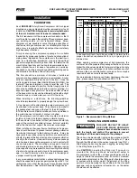
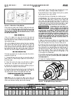
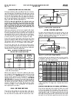
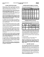
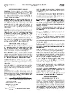
PARALLEL ALIGNMENT
6.
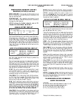
To.check.parallel.alignment,.as.shown.in.Figure.7,.reposi-
tion.dial.indicator.so.the.stem.is.in.contact.with.the.rim.of.the.
compressor.hub,.as.shown.in.Figure.8.
Check.the.dial.indicator.to.be.sure.that.the.indicator.stem.is.
slightly.loaded.so.as.to.allow.movement.in.both.directions.
7.
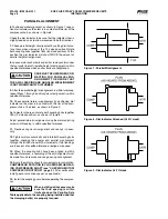
Check.parallel.height.misalignment.by.setting.dial.indica-
tor.at.zero.when.viewed.at.the.12.o’clock.position..Rotate.
both.coupling.hubs.together.180
O
.(6.o’clock.position)..At.this.
position.the.dial.indicator.will.show.TWICE.the.amount.of.
parallel.height.misalignment...
8.
Loosen.motor.anchor.bolts.and.add.or.remove.shims.under.
the.four.motor.feet.until.parallel.height.misalignment.is.within.
specified.tolerance.when.anchor.bolts.are.retightened.
CARE MUST BE USED WHEN COR-
RECTING FOR PARALLEL MIS-
ALIGNMENT TO ENSURE THAT
THE AXIAL SPACING AND ANGULAR MISALIGNMENT
IS NOT SIGNIFICANTLY DISTURBED.
9.
After.the.parallel.height.misalignment.is.within.tolerance,.
repeat.Steps.1.through.5.until.angular.misalignment.is.within.
specified.tolerance.................
..........
10.
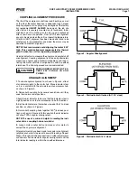
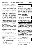
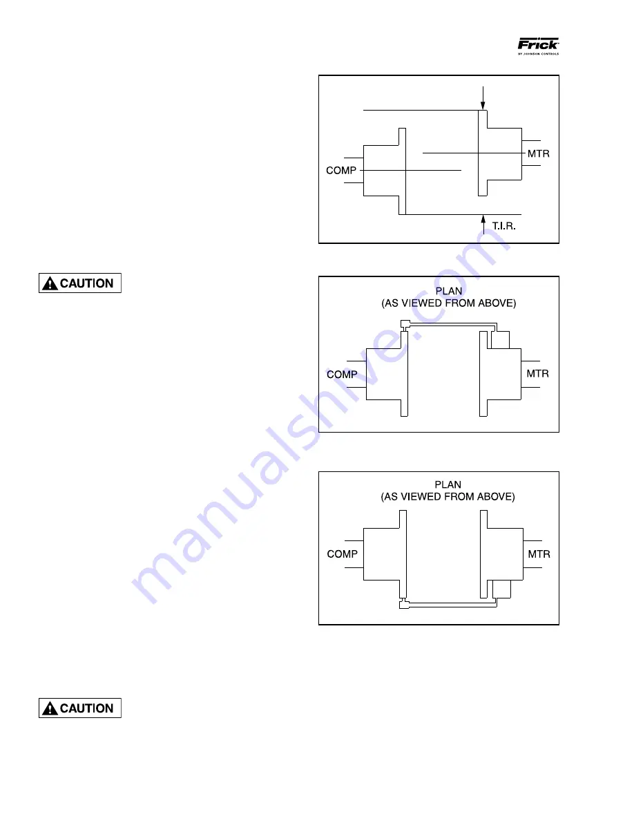
Check.parallel.lateral.misalignment.by.positioning.dial.
indicator.so.the.stem.is.in.contact.with.the.rim.of.the.com-
pressor.hub.at.3.o’clock,.as.shown.in.Figure.9.
Set.indicator.at.zero.and.rotate.both.coupling.hubs.together.
180
O
.(9.o’clock.position),.as.shown.in.Figure.8.
Adjust.parallel.lateral.misalignment.using.the.motor.adjusting.
screws.until.reading.is.within.specified.tolerance.
11.
. Recheck. angular. misalignment. and. realign. if. neces-
sary.
12.
Tighten.motor.anchor.bolts.and.rotate.both.coupling.hubs.
together,. checking. the. angular. and. parallel. misalignment.
through.the.full.360
O
.travel.at.90
O
.increments..If.dial.readings.
are.in.excess.of.specified.tolerance,.realign.as.required.
13.
.When. the. coupling. hubs. have. been. aligned. to. within.
specified.tolerance,.a.recording.of.the.cold.alignment.must.
be.made.for.unit.records.and.usage.during.hot.alignment.
14.
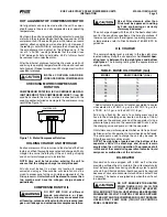
Bump.the.motor.to.check.for.correct.compressor.rotation..
COMPRESSOR ROTATION IS CLOCKWISE WHEN FAC-
ING COMPRESSOR SHAFT (see “CHECKING MOTOR/
COMPRESSOR ROTATION”, page 9).
After. verification,.
install.gear.or.disk.drive.spacer,.as.applicable.
15.
.Install.the.coupling.guard.before.operating.the.compres-
sor.
When installing drive spacer, make
sure that hub spacing is within
limits shown on the Coupling Data
Table applicable to the coupling being installed and that
the clamping bolt(s) are properly torqued.
Figure 7 - Parallel Misalignment
Figure 8 - Dial Indicator Attached (At 9 O’clock)
Figure 9 - Dial Indicator At 3 O’clock


