


RXB PLUS ROTARY SCREW COMPRESSOR UNITS
INSTALLATION
070.101-IOM (JAN 13)
Page 12
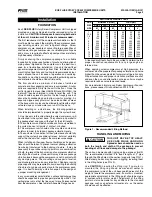
1.
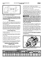
The.thermosyphon.oil.cooler.
is.supplied.with.the.oil.side.piped.
to.the.compressor.unit.and.stub.
ends.supplied.on.the.refrigerant.
side.
2.
. A. three-way. oil. temperature.
control. valve. is. required. where.
condensing. temperature. is. ex-
pected.to.go.below.65
O
F.
3.
A.refrigerant-side.safety.valve.
is. required. in. this. location. only.
when.refrigerant.isolation.valves.
are.installed.between.the.cooler.
and. thermosyphon. receiver.. If.
no. valves. are. used. between.
the. cooler. and.TSOC. receiver,.
the. safety. valve. on. the.TSOC.
receiver.must.be.sized.to.handle.
the.volume.of.both.vessels..Then,.
the. safety. valve. on. the. cooler.
vent.(liquid.refrigerant.side).can.
be.eliminated.
4.
The. system. receiver. must.
be.below.the.thermosyphon.re-
ceiver.in.this.arrangement.
Figure 14
Extra caution should be used when
servicing an oil separator with this
arrangement. If the oil cooler is
valved off from an oil separator which has been evacuated
for servicing, then the oil cooler could relieve into the
separator vessel if the 75 psi delta p setpoint is exceeded.
Other.units,.which.do.not.use.this.special.safety.valve.ar-
rangement,.will.have.factory.mounted.safety.valves.on.the.
shell. side. of. the. oil. cooler. which. the. installing. contractor.
should.pipe.into.house.safety.systems.designated.suitable.
for.oil.relief.
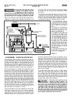
The.component.and.piping.arrangement.shown.in.Figure.14.
is.intended.only.to.illustrate.the.operating.principles.of.ther-
mosyphon.oil.cooling..Other.component.layouts.may.be.better.
suited.to.a.specific.installation..Refer.to.publication.070-900E.
for.additional.information.on.Thermosyphon.Oil.Cooling.
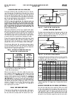
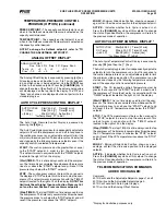
ECONOMIZER - HIGH STAGE (OPTIONAL)
The.economizer.option.provides.an.increase.in.system.ca-
pacity.and.efficiency.by.subcooling.liquid.from.the.condenser..
through.a.heat.exchanger.or.flash.tank.before.it.goes.to.the.
evapora.tor..The.subcooling.is.provided.by.flashing.liquid.in.
the.economizer.cooler.to.an.intermediate.pressure.level.The.
intermediate.pressure.is.provided.by.a.port.located.part.way.
down.the.compres.sion.process.on.the.screw.compressor.
As.the.screw.compressor.unloads,.the.economizer.port.will.
drop.in.pressure.level,.eventually.being.fully.open.to.suction..
Because.of.this,.an.output.from.the.microproces.sor.is.gener-
ally.used.to.turn.off.the.supply.of.flashing.liquid.on.a.shell.and.
coil.or.DX.economizer.when.the.capacity.falls.below.approxi-
mately.45%-60%.capacity.(85%-90%.slide.valve.position)..
This.is.done.because.the.compressor.will.be.more.efficient.
operating.at.a.higher.slide.valve.position.with.the.economizer.
turned.off,.than.it.will.at.a.low.slide.valve.position.with.the.
economizer.turned.on..Please.note.however.that.shell.and.
coil.and.DX.economizers.can.be.used.at.low.compressor.
capaciti.es.in.cases.where.efficien.cy.is.not.as.important.as.
ensuring.that.the.liquid.supply.is.subcooled..In.such.cases,.
the.economi.zer.liquid.solenoid.can.be.programmed.to.be.left.
open.whenever.the.com.pressor.is.running.
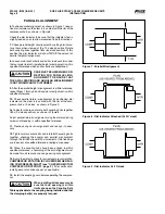
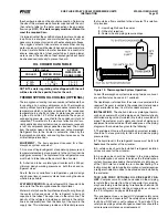
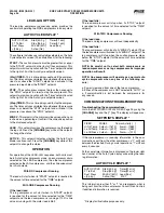
Due. to. the. tendency. of. the. port. pressure. to. fall. with. de-
creasing. compressor. capacity,. a. back-pressure. regulator.
valve. (BPR). is. generally. required. on. a. flash. economizer.
system.(Figure.17).in.order.to.maintain.some.preset.pressure.
dif.ference.between.the.subcooled.liquid.in.the.flash.vessel.
and.the.evaporato.rs..If.the.back-pressure.regulator.valve.is.
not.used.on.a.flash.economizer,.it.is.possible.that.no.pressure.
difference.will.exist.to.drive.liquid.from.the.flash.vessel.to.the.
evaporators,.since.the.flash.vessel.will.be.at.suction.pressure..
In.cases.where.wide.swings.in.pressure.are.anticipated.in.
the.flash.econo.mizer.vessel,.it.may.be.necessary.to.add.an.
outlet.pressure.regulator.to.the.flash.vessel.outlet.to.avoid.
overpressurizing. the. economizer. port,. which. could. result.
in.motor.overload..Example:.A.system.feeding.liquid.to.the.
flash.vessel.in.batches.
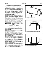
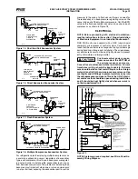
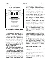
The.recommended.economizer.systems.are.shown.below..
Notice.that.in.all.systems.there.should.be.a.strainer.(STR).
and.a.check.valve.(VCK).between.the.economizer.vessel.
and.the.economizer.port.on.the.compressor..The.strainer.
prevents.dirt.from.passing.into.the.compressor.and.the.check.
valve.prevents.oil.from.flowing.from.the.compressor.unit.to.
the.econo.mizer.vessel.during.shutdown.
Other than the isolation valve
needed for strainer cleaning, it is
essential that the strainer be the
last device in the economizer line before the compres sor.
Also, piston-type check valves are recom mended for
installation in the economizer line, as opposed to disc-
type check valves. The latter are more prone to gas-
pulsation-induced failure. The isolation and check val ves
and strainer should be located as closely as possible to
the compressor, preferably within three feet.


