


RXB PLUS ROTARY SCREW COMPRESSOR UNITS
MAINTENANCE
070.101-IOM (JAN 13)
Page 38
4.
.Close.the.service.valve.located.between.the.compressor.
and.the.liquid.injection,.thermal.expansion.valve.
5.
.Carefully.loosen.the.capscrews.securing.the.strainer.cover.
to.the.strainer...Allow.pressure.to.relieve.slowly.
6.
.When.all.entrapped.refrigerant.has.been.relieved,.care-
fully.remove.the.loosened.capscrews.(as.liquid.refrigerant.
is. some.times. caught. in. the. strainer),. strain.er. cover,. and.
strainer.basket.
7.
.Wash.the.strainer.basket.and.cover.in.sol.vent.and.blow.
them.clean.with.air.
8.
.Reassemble.the.strainer.
9.
. Open. the. service. valve. between. the. compressor. and.
the.liquid.injection.thermal.expansion.valve.and.check.for.
leakage.
10.
.Screw.out.the.manual.solenoid.valve.stem.
11.
.Carefully.open.the.liquid.supply.service.valve.
12.
.Leak.test.
13.
.Open.suction.and.discharge.valves.and.readjust.suc-
tion.check.valve.bypass.(if.required)..Close.the.disconnect.
switches. for. the. compressor. and. (if. applicable). oil. pump.
motor.starters.
14.
.Start.the.unit.
COALESCER FILTER ELEMENT
When. changing. the. coalescer. filter. element,. it. is. recom-
mended.that.the.oil.and.oil.filter(s).be.changed..Applicable.
strainer.elements.should.be.removed.and.cleaned.
1.
.Refer.to.
CHANGING OIL,
.Steps.1.thru.8.
2.
.Remove.coalescer.head.and.gasket..Discard.the.gasket.
3.
.Remove.and.retain.the.nut.securing.the.coalescer.filter.
retainer.
4.
. Remove. the. retainer,. coalescer. filter. element,. and. 2.
O-rings...Discard.the.filter.element.
5.
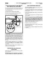
.Install.the.new.coalescer.filter.element.
Seat the element in center of locat-
ing tabs on separator bulkhead.
6.
. Replace. the. coalescer. filter. retainer. and. nut..
DO NOT
OVERTIGHTEN THE NUT.
Torque. values. for. nut. are:. 15.
ft-lb.for.models.12.and.15;.17.ft-lb.for.19.and.24;.and.21.ft-lb.
for.30–50..Install.jam.nut.
7.
.Install.new.head.gasket.and.replace.the.coalescer.head.
8.
.Tighten.the.head.bolts...
NOTE: WHEN THE COM PRES-
SOR UNIT IS REPRESSURIZED, RE TIGHTEN THE HEAD
BOLTS TO PREVENT THEM FROM LOOSENING.
9.
.Refer.to.
CHANGING OIL,
.Steps.9.thru.14.
CHANGING OIL
DO NOT MIX OILS of different
brands, manufacturers, or types.
Mixing of oils may cause excessive
oil foaming, nuisance oil level cutouts, oil pressure loss,
gas or oil leakage and catastrophic compressor failure.
Shut.down.the.unit.when.changing.oil...At.the.same.time,.
all.oil.filter.cartridges.must.be.changed.and.all.oil.strainer.
elements.removed.and.cleaned..The.procedure.is.as.follows:
1.
.Push.
[STOP]
.key.to.shut..down.the.unit.
2.
. Open. the. disconnect. switch. for. the. compressor. motor.
starter.and.(if.applicable).oil.pump.motor.starter..
3.
. Close. the. discharge,. and. liquid. injec.tion. (if. applicable).
service.valves.
4.
.
SLOWLY
.vent.the.separator.to.low-side.system.pres.sure.
using.the.suction.check.valve.bypass..Close.suction.valve.
and.suction.check.valve.bypass...
NOTE: Recover or transfer
all refrigerant vapor in accordance with local ordinances
before opening to atmosphere.
The.separator.
MUST
.be.
equalized.to.atmospheric.pressure..
Oil-entrained refrigerant may vapor-
ize, causing a separator pressure
increase. Repeat venting and re-
covery procedure if neces sary.
5.
.Open.the.drain.valve(s).located.on.the.underside.of.the.
separator.and.drain.the.oil.
6.
.Drain.the.oil.filter,.strainers,.and.oil.cooler,.if.applicable.
7.
.Remove.and.install.new.oil.filter.cartridge(s)..Inspect.check.
valve.in.the.bottom.of.the.filter.housing.to.ensure.that.the.
parts.are.in.good.condition.
8.
.Remove,.clean,.and.reinstall.strainer.ele.ments.in.strainers.
9.
.Evacuate.the.unit.to.29.88".Hg.(1000.microns).
10.
.Open.the.suction.service.valve.and.pressurize.the.unit.
to. system. suction. pressure.. Close. the. suction. valve. and.
leak.test.
11.
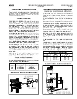
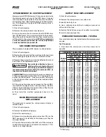
.Add.oil.by.attaching.suitable.pressure-type.hose.to.the.
oil-charging.valve.located.on.top.of.the.separator..Using.a.
pressure-type.oil.pump.and.recommended.Frick.oil,.open.
the.charging.valve.and.fill.separator.until.oil.level.is.midway.
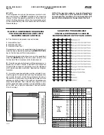
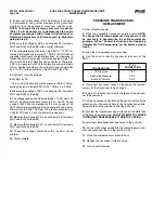
in.the.top.sight.glass..The.following.table.gives.approximate.
oil.charge.quantities.
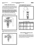
TABLE BASIC OIL CHARGE
RXB MODEL
BASIC CHARGE*(Gal.)
12.&.15
10
19.&.24
14
30.&.39
17
50
21
*.Add.oil.volume.for.external.oil.cooler,.according.to.cooler.
size.selected:.6.x.5.TSOC.-.4.gal.;.6.x.5.WCOC.-.5.gal.;.8.x.
5.TSOC.-.6-1/2.gal.;.and.8.x.5.WCOC.-.8.gal.
12.
.Open.the.suction,.discharge,.and.liquid.injec.tion.service.
valves..Readjust.suction.check.valve.bypass.
13.
.Close.the.disconnect.switch.for.the.compressor.motor.
starter.and.(if.applicable).oil.pump.motor.starter.
14.
.Start.the.unit.


