RXB PLUS ROTARY SCREW COMPRESSOR UNITS
INSTALLATION
070.101-IOM (JAN 13)
Page 7
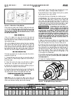
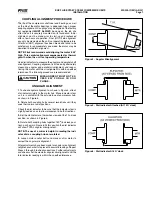
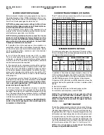
Figure 4 - Angular Misalignment
COUPLING ALIGNMENT PROCEDURE
The.life.of.the.compressor.shaft.seal.and.bearings,.as.well.
as.the.life.of.the.motor.bearings,.is.dependent.upon.proper.
coupling.alignment..Couplings.may.be.aligned.at.the.factory.
but. realignment.
MUST ALWAYS
. be. done. on. the. job. site.
after.the.unit.is.securely.mounted.on.its.founda.tion..Initial.
alignment. must. be. made. prior. to. start-up. and. rechecked.
after.a.few.hours.of.operation..Final.(HOT).field.alignment.
can.only.be.made.when.the.unit.is.at.operating.tempera.ture...
After.final.(HOT).alignment.has.been.made.and.found.to.be.
satisfac.tory.for.approximately.one.week,.the.motor.may.be.
dowelled.to.maintain.align.ment.
NOTE: Frick recommends cold aligning the motor .005”
high. This cold misalignment compensates for thermal
growth when the unit is at operating temperature.
Use.dial.indicators.to.measu.re.the.angular.and.parallel.shaft.
misalign.ment..Coupling.alignment.is.attained.by.alternately.
measuring. angular. and. parallel. misalignment. and. reposi-
tioning.the.motor.until.the.misalignment.is.within.specified.
tolerances..The.following.procedure.is.recommended.
MISALIGNMENT MUST NOT EX-
CEED .004” FOR ALL CH COU-
PLINGS.
ANGULAR ALIGNMENT
1.
.To.check.angular.alignment,.as.shown.in.Figure.4,.attach.
dial.indicator.rigidly.to.the.motor.hub..Move.indicator.stem.
so.it.is.in.contact.with.the.outside.face.of.compressor.hub,.
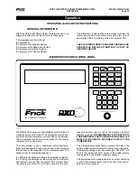
as.shown.in.Figure.5.
2.
.Rotate.both.coupling.hubs.several.revolutions.until.they.
seek.their.normal.axial.positions.
Check.the.dial.indicator.to.be.sure.that.the.indicator.stem.is.
slightly.loaded.so.as.to.allow.movement.in.both.direc.tions.
3.
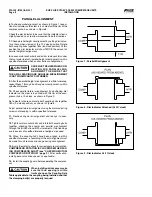
.Set.the.dial.indicator.at.zero.when.viewed.at.the.12.o’clock.
position,.as.shown.in.Figure.5.
4.
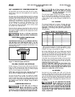
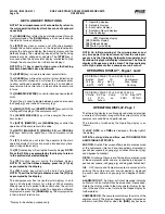
.Rotate.both.coupling.hubs.together.180
O
.(6.o’clock.posi-
tion),.as.shown.in.Figure.6..At.this.position.the.dial.indicator.
will.show.TOTAL.angular.misalignment.
NOTE: The use of a mirror is helpful in reading the indi-
cator dial as coupling hubs are rotated.
5.
.Loosen.motor.anchor.bolts.and.move.or.shim.motor.to.
correct.the.angular.misalignment..
After.adjustments.have.been.made.for.angular.mis.align.ment.
retighten.anchor.bolts.to.prevent.inac.curate.read.ings..Repeat.
Steps.3.through.5.to.check.corrections..Further.adjustments.
and.checks.shall.be.made.for.angular.misalignment.until.the.
total.in.dicator.reading.is.within.the.specified.tolerance.
Figure 5 - Dial Indicator Attached (At 12 O’clock)
Figure 6 - Dial Indicator At 6 O’clock


