


RXB PLUS ROTARY SCREW COMPRESSOR UNITS
MAINTENANCE
070.101-IOM (JAN 13)
Page 46
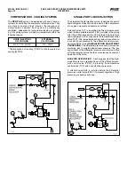
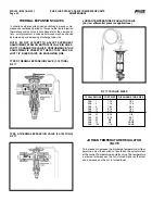
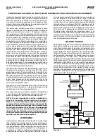
PRESSURE TRANSDUCERS -
REPLACEMENT
1.
.Shut.off.control.power.
2.
. Close. the. applicable. transducer. isolation. valve.
NOTE:
To change the discharge pressure transducers, it will
be necessary to depressurize the entire compressor
package. Follow “General Instructions For Replacing
Compressor Unit Components” (p. 36) before going to
step 3.
3.
.Open.the.microprocessor.console.door.
4.
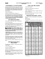
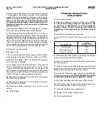
. Use. the. chart. to. identify. transducer. terminals. of. the.
SBC.
TRANSDUCER
P & I
CONNECTION
Oil.Pressure
PE-1....
Discharge.Pressure
PE-3....
Suction.Pressure
PE-4
5.
. Disconnect. transducer. leads. by. loosening. the. terminal.
screws.for.the.transducer.to.be.changed.
6.
.Tape.a.3.ft..length.of.pull.wire.to.the.leads.of.the.trans.du-
cer.to.be.removed.
7.
.Pull.the.transducer.leads.through.the.conduit.until.pull.wire.
extends.out.of.the.conduit.hole.in.the.transducer.manifold..
Separate.the.transducer.leads.from.the.pull.wire.
8.
.Unscrew.the.transducer.using.a.wrench.on.the.metal.hex.
at.the.base.of.the.transducer..
DO NOT ATTEMPT TO LOOSEN
OR TIGHTEN TRANSDUCERS BY THEIR TOP CASING.
9.
.Install.new.transducer.and.tape.leads.to.the.pull.wire.
10.
.Pull.new.transducer.leads.into.the.microprocessor.con-
sole.and.reconnect.them.to.the.terminal.strip.
11.
.Close.the.microprocessor.console.door.
12.
.Reopen.the.transducer.isolation.valve.
13.
.Turn.on.control.power.
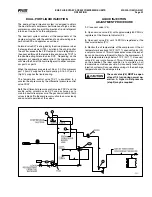
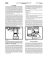
2.
.Isolate.suction.transducer.PE-4.from.the.unit.and.open.
it. to. atmosphere. using. valves. provided. at. the. transducer.
manifold.Close. the. applicable. transducer. isolation. valve...
NOTE: To change the discharge pressure transducer
(PE-3), it will be necessary to depressurize the entire
compressor package. Follow “General Instructions For
Replacing Compressor Unit Components” (p. 36) before
going to step 3.
3.
.Measure.the.voltage.of.PE-4.on.connector.P4.(terminals.
WHT.and.BLK).on.the.SBC.with.a.digital.voltmeter.
4.
.The.voltage.reading.should.be.1.48.VDC.to.1.72.VDC.at.
standard.atmospheric.pressure.(14.7.PSIA.or.0.PSIG)..When.
checking.transducers.at.higher.elevations,.an.allowance.in.
the.readings.must.be.made.by.subtracting.approximately.0.02.
VDC.per.1000.feet.of.elevation.above.sea.level...Therefore,.
if.PE-4.is.measured.at.5000.feet.elevation.under.relatively.
normal.weather.conditions,.the.output.voltage.should.differ.
by.0.10.VDC.to.read.between.1.38.VDC.and.1.62.VDC.
5.
Subtract.1.from.the.voltage.
6.
.Multiply.by.25.
7..This.result.is.the.absolute.suction.pressure.(PSIA)..The.Op-
erating.display.will.indicate.PSIG.(14.7.PSIA.=.0.0.PSIG).
8.
.Measure.the.voltage.of.PE-1.on.connector.P4.(terminals.
WHT.and.BLK).on.the.SBC.
9.
.The.voltage.reading.should.be.between.1.1.VDC.and.1.29.
VDC.at.standard.atmospheric.pressure..PE-1.and.PE-3.have.
a.span.of.300.PSI.as.compared.to.PE-4.with.a.span.of.100.
PSI..Therefore,.atmospheric.pressure.changes.have.a.lesser.
effect.which.is.0.0067.VDC.per.1000.feet.of.eleva.tion.and.
0.00067.VDC.per.0.1.inch.Hg.baro.metric.deviation.
10.
.Measure.the.voltage.of.PE-3.on.connector.P4.(terminals.
WHT.and.BLK).on.the.SBC.
11.
.Measure.the.voltage.of.PE-1.on.connector.P4.(terminals.
WHT.and.BLK).on.the.SBC.
12.
.These. two. voltages. should. be. within. .04.VDC. of. one.
another.
13.
.Test.complete.


