DINAMAP*
Compact
Vital Signs Monitor
40
XIX. Ensure that the Temperature Calibration Plug (Part No 320-635) is connected between
pins 1 and 2 of the temperature probe socket on the UUT.
XX. If UUT is set to read temperature in °C enter service mode PIN CODE 2 2 1 3. Select
TEMP followed by °C/°F, when unit displays message ‘ Confirm Trend data will be lost
Y/N’ select YES. Switch UUT off then on and confirm °F LED is lit.
XXI. Select TEMP from the main menu on the UUT LCD and confirm that reading displayed
after approximately 60 seconds is 98.6°F.
XXII. If reading is not 98.6°F then repeat from paragraph IX.
XXIII. Proceed to Section 3.3.6.4.
3.3.6.3 Temperature Calibration Procedure (Software Version 8613-V4.1)
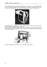
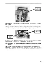
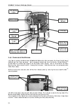
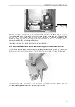
I. Remove screws in recessed handle of the UUT and drop the front cover forward to reveal
potentiometers RV2 and RV3 on the Main Board.
II. Connect AC Adapter to UUT DC input socket and switch on UUT.
III. Connect Temperature Calibration Plug to the temperature probe socket on UUT .
IV. Whilst depressing STAT, START and Alarm Mute buttons on front panel, switch on UUT.
Confirm UUT LCD is showing the Super Service Menu.
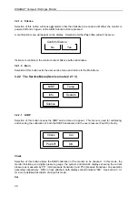
V. Select PTEMP from Super Service Menu, followed by PLUG.
VI. Adjust RV2 on UUT Main Board to obtain an edge count for the Calibration PLUG of 957.
VII. Remove calibration resistor from UUT temperature socket
Note:
Test paragraphs VIII to IX must be carried out immediately after the preceding paragraph
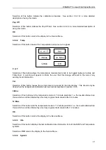
VIII. Select 98 on the menu corresponding to the 98°F internal calibration point. Adjust RV3
until the number of edges reported for the 98 point is 948
±
1 edges.
IX. Select 54 on the menu corresponding to the 54°F internal calibration point. Confirm
number of edges reported is 57
±
6 edges.
X. Turn unit off then on.
XI. Ensure that the Temperature Calibration Plug (Part No 320-635) is connected to the
temperature probe socket on the UUT.
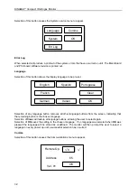
XII. If UUT is set to read temperature in °C enter service mode PIN CODE 2 2 1 3. Select
TEMP followed by °C/°F, when unit displays message ‘ Confirm Trend data will be lost
Y/N’ select YES. Switch UUT off then on and confirm °F LED is lit.
XIII. Select TEMP from the main menu on the UUT LCD and confirm that reading displayed
after approximately 60 seconds is 98.6°F.
XIV. If reading is not 98.6°F then repeat from paragraph I.
3.3.6.4 Calibration Time Stamp
I. Enter Service Mode PIN code 2 2 1 3.
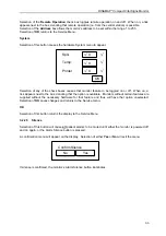
II. From the sub menu select TEMP.
III. To record the current time and date as the time and date of calibration select CAL.
IV. Switch off UUT.
V. Switch on UUT
VI. Enter Service Mode PIN code 2 2 1 3.
VII. Select INFO and confirm date of NIBP calibration and time and date of TEMP calibration
are correct.
Carry out Manual Release Test Procedure as per section 4 prior to release of unit for clinical use.

