DINAMAP*
Compact
Vital Signs Monitor
22
Diodes D24 and D25 provide a power supply line VDC_OP which is present whenever a supply is
available. This supply is used exclusively for IC16, a programmable voltage regulator with internal
comparator. IC16 performs two functions. First, its internal comparator compares the sampled line
input voltage DC_INPUT to an internal reference level. When the DC_INPUT is below approximately
10.4 volts, IC16 turns off TR14 to indicate to the PIC that there is no valid external DC input. The
second function of IC16 is to generate a precision voltage supply from VDC_OP, set by R5 & R9 to 4.5
volts. This voltage is connected to the BATT_BACKUP line by D13, D23 preventing the voltage from
entering the NiCd backup battery. This battery, B1, has a nominal terminal voltage of 3.6 volts and is
trickle charged form the +15.1 volt supply when the system is powered.
The VRAW supply, which is nominally 14.8 volts when operating from an external line voltage or 10.4
to 13.6 volts when operating from battery, is used to generate the other power supply lines. The
monitor’s power on switch is routed directly to the PIC which controls the set up sequencing of the
power rails. The PIC switches on the +5VD line then the +VDISP line, the 12 volt supplies are
controlled by the system processor which turns them on after the +5VD supply is stable.
VRAW enters IC7, a step down DC to DC converter which is used to produce the +5VD digital line.
The 5 volt logic supply IC7 is controlled by the PSU_INH signal from the PIC. VRAW also connects to
IC17 to produce the +4.5 volt LED display VDISP, which is controlled by the PIC signal
ENABLE_VDISP.
The 12 volt line and other supplies are controlled by the 12V_ON signal from the system processor on
the Main Board. When this pin is at a high logic level, TR9 is turned on, as is p-channel FET TR10.
This causes the VRAW supply to enter IC8, a boost switching regulator. R41 & R42 set the output
voltage of the flyback converter to 14.5 volts, which is further regulated by linear regulator IC9 to
produce the pump and valve 12VV line and linear regulator IC18 to produce the analogue
12VR line. The output of TR10 also feeds the inverting switching regulator IC10, which
produces a -14 volt supply to linear regulator IC19 which in turn produces the analogue supply -12VR
line. A sample of the +12VV line is taken by R44 & R45, producing the PUMP_V signal, while a sample
is taken 12VR and -12VR lines by R47 & R48 producing the ANALOGUE_V signal. These are
measured by ADCs inside the PIC to confirm the operation of the power supplies.
2.4.7 Audio Amplifier
User warning sounds are generated by the power supply board PIC as a pulse width modulated digital
signal AUDIO_FREQ. This signal is fed to all the inputs of the quad bilateral switch IC14, their outputs
being connected together via a resistor ladder to produce a switched gain summing amplifier IC6 The
gain elements are operated by the PIC signal A_GAIN0-3, together providing a 4-bit (16 level) volume
control. The output of the summing amplifier IC6 also applies band-pass filtering to the audio signal.
The circuit around IC6b sets the upper breakpoint of the filter, while the circuit on the input to the final
amplifier IC15 sets the lower breakpoint and provides amplification for the speaker.
2.4.8 Alarm and Communication Interfaces
The remote alarm signal originates from the system processor on the Main Board, from where it is logic
ORed with the FAILSAFE signal, inverted and sent as the REMOTE_ALARM signal to the power supply
board. The signal controls n-channel FET TR11 to drive the coil of the relay RL1/2. The switch side of
the relay contains both normally open and normally closed contacts which are separated from the
monitor electronics via an isolation barrier. A dual pole dual throw relay is used, but its switch elements
are connected in parallel to provide a single pole dual throw action with increased current capacity.
Communications signals use the RS232 bi-directional serial format. Digital TTL level signals from the
system processor are converted to RS232 level signals on the power supply board by IC13, which
generates the necessary positive and negative voltage swings. In addition, inverted TTL data transmit
and receive lines are provided. A 5 volt supply is also made available to the serial port, this being
protected by a 0.1 amp thermal resetable fuse.
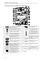
2.4.9 User Controls
The user controls are comprised of four push buttons; power, stat, NIBP start/stop and alarm silence,
and the rotor control. When the rotor control is turned, it operates an optical encoder producing a Gray


