Jets™ 25MBA Vacuumarator™ pump
Tel. +47 70 03 91 00
www.jetsgroup.com
Product No. 200025004
Doc. Rev.: 22 (2021-06-08)
7
Installation Steps
1. Do not remove the protective covering on the pumps inlet and outlet until connecting the pipes.
2. Flush the piping system and any connections to the pump to ensure that all foreign objects have been removed prior to connection.
3. The piping system should be leak tested before connecting the pump.
4. Connect the inlet pipe to the suction side of the pump.
5. Connect the outlet pipe to the pressure side of the pump.
6. Remove the fan cover. Manually rotate the shaft by hand turning the fan. Ensure that all moving parts rotate freely without obstruction. Re-fit
the fan cover.
7. Ensure that the pump is placed on a flat surface and that all four fundament flanges are in contact with the surface.
8. Secure the pump to the base plate.
Electrical Installation
Prior to connecting any electrical wiring, ensure that all electrical safety warnings are read and understood. Take the necessary precautions to
prevent accident, injury or damage to equipment.
Electrical connection details are located on the motor name plate.
3.1 Warning
All wiring should be performed by a licensed or certified electrician.
3.28 Warning
Never work on the equipment when power is applied.
Electrical Connection:
1. Ensure that the pump is protected against overload.
2. When connecting the pump, be sure to ground the motor.
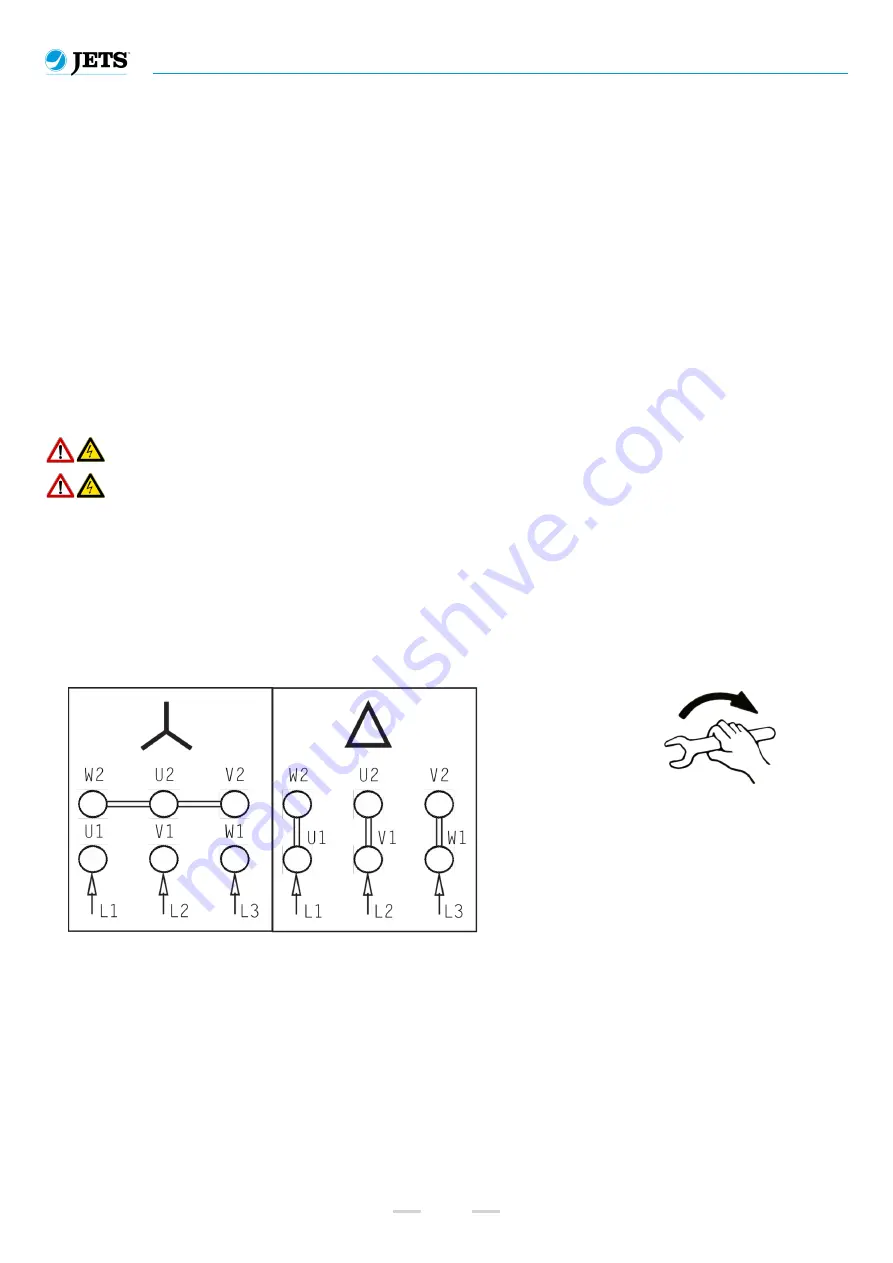
3. Connect the electrical wiring as per the connection details on the products name plate.
4. Check that the rotation direction of the shaft is correct in relation to the rotation direction on the serial number label. Note that incorrect
rotation may result in damage to the pump.
Electrical Connection Diagram
M 4 = 0.8 - 1.2 Nm
M 5 = 1.8 - 2.5 Nm
M 6 = 2.7 - 4.0 Nm
M 8 = 5.5 - 8.0 Nm
M10 = 9.0 - 13.0 Nm


