background image

Configuring the TM-2030GE Camera

TM/

TMC/RM/RMC-2030GE

- 15 -

Figure 19. Gain Settings Checkbox Cleared

If the camera has a high gain setting it takes longer to  balance the channel. Channel Balance may not 
work properly if a high-speed shutter is used under a low-frequency light, such as a fluorescent light. 
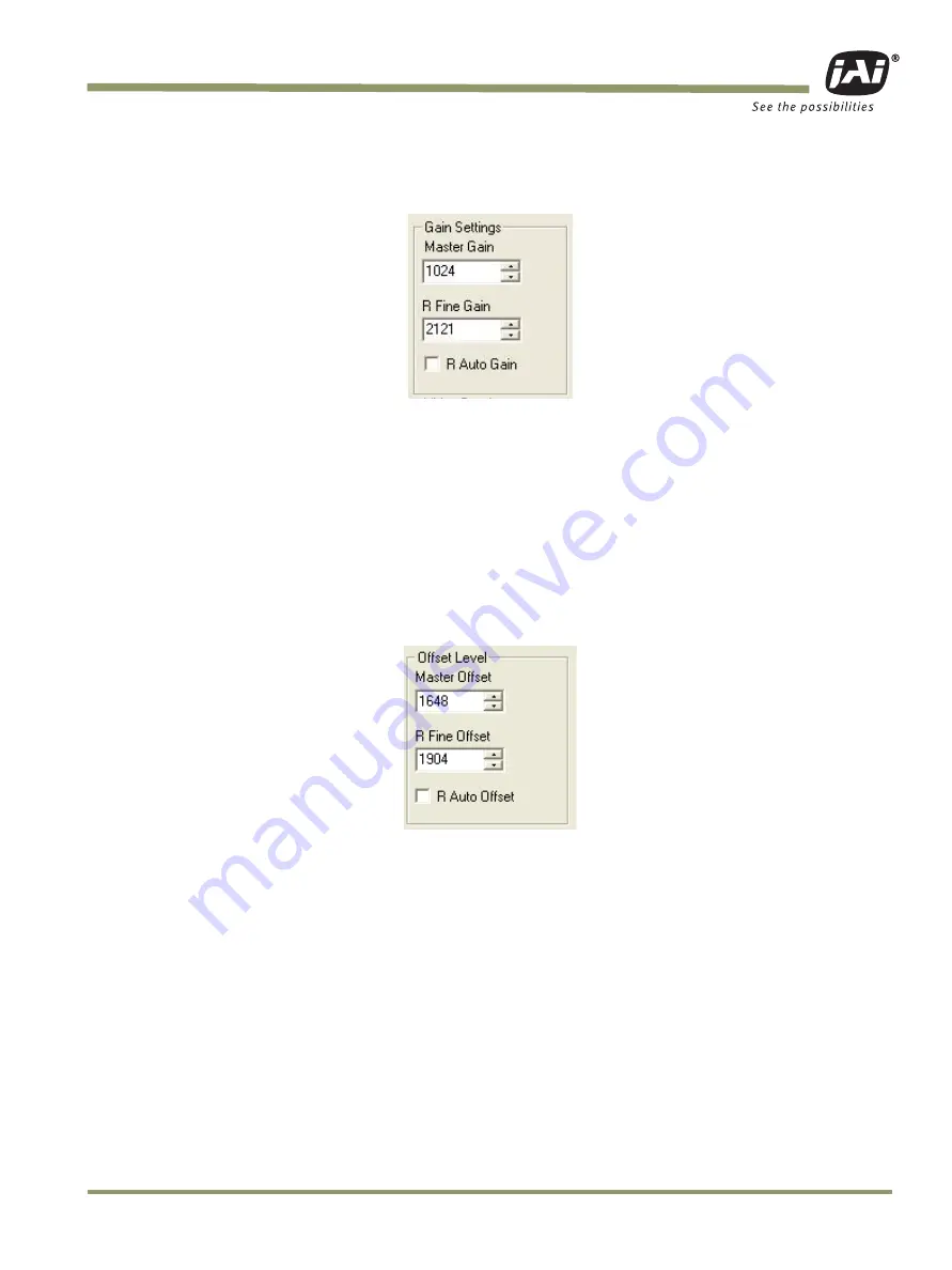
3.4.4  Offset Level 

The Channel A offset level is the master,  channel B is the slave. The offset level box, shown in 
Figure 20, allows you to change Channel A offset voltage. To change the value, click on the up or 
down arrow, or enter the value directly into the box. The camera itself automatically adjusts Channel 
B offset voltage, every other frame. 

Figure 20. Offset Level.


Summary of Contents for RM-2030GE

Page 1: ...User s Manual Document Version C Document P N 10446 TM TMC 2030GE Progressive Scan Cameras ...

Page 2: ...TM TMC RM RMC 2030GE ii ...

Page 3: ...cts bearing the CE mark have been declared to be in conformance with the applicable EEC Council Directives However certain factory installed options or customer requested modifications may compro mise electromagnetic compatibility and affect CE compliance Please note that the use of interconnect cables that are not properly grounded and shielded may affect CE compliance Contact JAI Inc Application...

Page 4: ...oved by the party responsible for FCC compliance could void the user s authority to operate the equipment TM 2030GE Series Operation Manual JAI Inc 625 River Oaks Parkway San Jose CA 95134 Tel 408 383 0300 Tel 800 445 5444 Fax 408 383 0301 E mail imaging jai com www jai com October 12 2007 ...

Page 5: ...TM TMC RM RMC 2030GE v ...

Page 6: ...TM TMC RM RMC 2030GE vi ...

Page 7: ...3 1 Setup 8 3 1 1 To use the integrated GigE camera software 9 3 2 Configuring the Imager 10 3 2 1 GUI Features 11 3 3 Configuring the Internal Frame Grabber 11 3 4 Modes 11 3 4 1 Check the Current Camera Setting 11 3 4 2 Exposure Control 12 3 4 3 Gain Settings 14 3 4 4 Offset Level 15 3 4 5 Look Up Table 16 3 4 6 Memory Pages 16 3 4 7 Free Running Mode 17 3 4 8 Externally Triggered 17 3 4 9 Inter...

Page 8: ...escription 41 8 2 Features 41 9 Installation 43 9 1 Getting Started 43 9 1 1 Unpacking Instructions 43 9 1 2 Components 43 9 1 3 Accessories and Options 43 9 2 Camera Setup 44 9 2 1 Heat Dissipation 44 9 2 2 Connector Pin Configurations 44 9 2 3 Power Supplies and Power Cable Setup 45 9 2 4 Attaching the Camera Lens 47 9 2 5 Adjustable Back Focus 47 10 Operation 48 10 1 Progressive Scanning 48 10 ...

Page 9: ... Exposure Mode 60 10 5 6 PWC PIV Mode 61 10 6 Camera Timing Charts 62 11 Troubleshooting 64 11 1 Problems and Solutions 64 11 1 1 Symptom No Video 64 11 1 2 Symptom Dark Video 64 11 1 3 Symptom Non Synchronized Video 64 11 1 4 Symptom Video does not Display Properly 64 11 1 5 Symptom Notebook Computer Driver Installation Problems 65 11 1 6 Information and Support Resources 65 12 Appendix 66 12 1 S...

Page 10: ...Table of Contents TM TMC RM RMC 2030GE x ...

Page 11: ...nerator Page 24 Figure 28 The Setup icon installs Dual Tap AccuPIXel v 2 5 x x 30 Figure 29 AccuPIXel Setup screen 30 Figure 30 The Add or Remove Programs utility can uninstall older software 31 Figure 31 Back of the TM TMC 2030GE 31 Figure 32 Main Dual Tap AccuPiXEL Window 32 Figure 33 Continuous mode operates the shutter based on the camera settings 33 Figure 34 The camera offers full scan or bi...

Page 12: ... 54 Example of TMC 2030GE Same as TM 2030GE 53 Figure 55 Output and Blooming 55 Figure 56 External Trigger Timing 57 Figure 57 Asynchronous Programmable External Trigger 58 Figure 58 Pulse Width Control Trigger 59 Figure 59 PIV Exposure Timing Table 60 Figure 60 PWC PIV Timing Table 61 Figure 61 Camera Timing Chart 62 Figure 62 Digital Data Output Order for Configuration 62 Figure 63 Field Video T...

Page 13: ...Table 2 GPIO Look Up Table Input Labels 22 Table 3 GPIO Look Up Table Output Labels 23 Table 4 TM TMC 2030GE Command List 25 Table 5 Command Responses 27 Table 6 12 Pin Connector 44 Table 7 Scan Area Start Points 50 Table 8 Asynchronous Mode Chart 61 Table 9 TM 2030GE Camera Specifications Table 66 ...

Page 14: ...List of Tables TM TMC RM RMC 2030GE xiv ...

Page 15: ...ence Manual These documents are part of the GigE software package and are added to your system when the soft ware is installed The software and documents are current for the TM 2030GE series as pertains to Cam2Net 1 3 Gigabit Ethernet Camera Interface The GigE interface provides an easy to connect high bandwidth imaging solution where video data is sent as IP packets over an industry standard GigE...

Page 16: ... the PC hard disk 1 4 2 Installing the Software To install the JAI GigE camera control software read and follow the directions included in the docu ment download card If the computer does not have Internet access call JAI Inc at 1 800 445 5444 to request the software on a CD ROM Install the software using the following steps 1 Open the folder JAI and run the JAI GigE 2 14 0 Installer exe file to i...

Page 17: ...ional dialog boxes 8 For information on other network card installs click Start JAI A S Cam2Net Documenta tion Cam2Net IP Device Drivers An Acrobat file is available with instructions to help guide you through the proper install 9 Go to Start Programs JAI AS Cam2Net Launch Coyote application to launch the cam era control tool 1 4 3 Uninstalling the Software To uninstall the JAI GigE camera control...

Page 18: ...t is shown in Table 1 on page 6 Both the Hirose and the network cable RJ 45 are illustrated in Figure 6 Verify that both LED s on the RJ 45 connector are green 2 Run the Camera Interface Application 3 Click Detect Assign a suitable IP address to the camera The window shown in Figure 2 appears Figure 4 Network Device Finder Window 4 Select the appropriate camera from the list similar to the window ...

Page 19: ... CPU In default mode the camera supports 2 x 2 color interpolation For better color performance the user can select 3 x 3 interpolation in the Camera Interface Application Return to the Acquisition tab of the Coyote previous screen and click Configure In the Advanced Configuration Window select the Pixel Type tab Make sure the camera is set to the proper color space and pixel depth and then click ...

Page 20: ...Table 1 lists the pin layout and describes the function of each pin The table lists the GPIO assignments for the relevant pins A magnified illustration of each pin s assignment follows in Figure 7 on page 7 Table 1 Hirose Connector Pin Assignment Pin Definition Description GPIO Assignment 1 GND Power ground 2 12V DC Power supply in 3 GND Analog ground video 4 Analog Video FoAuto iris lens drive O ...

Page 21: ...t cat5e UTP cables Cat6 cables are preferred If you wish to connect the camera directly to a PC you must use a cross over cable Refer to the Cam2Net User s Manual for details 1 Figure 8 Ethernet GigE Socket 1 JAI recommends the use of shielded cables to reduce emissions and for CE FCC compliance Double shielded cables further reduce emissions 1 9 2 10 8 3 11 12 7 4 5 6 GigE ...

Page 22: ...f you have a peer to peer connection between the TM 2030GE camera and your PC without network switches your packet size can be the default value 8128 bytes as shown in Figure 9 However if you are connecting the TM 2030GE to your PC through a network switch then you need to know the max imum packet size that your network switch supports Typically if your switch supports jumbo pack ets then you shou...

Page 23: ...quisition tab and click Configure The camera configuration dialog box displays 5 Select the GigE Camera Software tab This is the Integrated GigE Camera Software shown in Figure 11 The TM 2030GE camera operates in 8 bit 10 bit or 12 bit digital output mode The 8 bit 10 bit 12 bit selection is possible through the GigE integrated software To select the mode open the Configure page and select the Pix...

Page 24: ...ted GigE camera software that is part of the Cam2Net Camera Interface Application You can also use the dual tap AccuPiXEL GigE control tool but that will not update any internal grabber settings See Hardware Introduction on page 41 for a description of the different image settings of the camera Figure 11 Integrated GigE Camera Software ...

Page 25: ...he imager configuration you can set up that is window the internal frame grabber separately for example the Image Settings tab in the integrated camera software This has the added benefit of reducing unnecessary traffic on the GigE network and freeing bandwidth for other cameras 3 4 Modes This section includes examples of various types of setup actions available through the camera config uration d...

Page 26: ...igure 12 Advanced Configuration Port Communication 3 4 2 Exposure Control In Exposure Control under the GigE Camera software tab shown in Figure 13 you can specify the shutter mode and set the shutter speed and direct shutter values Figure 13 Exposure Control ...

Page 27: ... in Figure 15 allows you to select the specific shutter speed for manual shutter and Async shutter Manual shutter speed 0 is No Shutter mode Async shutter speed 0 is Async No Shutter mode Async shutter speed 9 is Async No Delay shutter mode pulse width control Direct Shutter allows you to select shutter speed for direct shutter count by the video line Figure 15 Shutter Speed The TM 2030GE camera h...

Page 28: ...n checkbox to enable gain channel balancing During the auto balance process the wording changes from Auto Gain Balance to Balancing Please wait one minute Figure 17 Gain Setting Control 3 4 3 b Auto Gain Control The checkbox stays marked for the duration of the channel balancing process and then clears After one minute a dialog box displays to verify the channel balance should proceed Figure 18 Co...

Page 29: ...tter is used under a low frequency light such as a fluorescent light 3 4 4 Offset Level The Channel A offset level is the master channel B is the slave The offset level box shown in Figure 20 allows you to change Channel A offset voltage To change the value click on the up or down arrow or enter the value directly into the box The camera itself automatically adjusts Channel B offset voltage every ...

Page 30: ... positive or negative box to choose an image option There is no LUT for 12 bit output 3 4 6 Memory Pages All the camera parameters such as shutter mode shutter speed gain offset level scan mode and LUT can be saved into seven available memory pages on the EEPROM in the camera The pages are numbered 0 6 The Load Page button loads the corresponding camera settings from the EEPROM while the write pag...

Page 31: ...u should now see a free running video stream 3 4 8 Externally Triggered The external trigger is sent through pin 6 of the 12 pin Hirose connector To use the software to enable the external trigger follow these steps 1 Change the GigE camera software shutter mode to Async Shutter 2 Set the GPIO look up table to Q4 I0 and Q5 1 3 4 9 Internally Triggered The camera control software includes pulse gen...

Page 32: ... tab of the Camera Interface Application dialog box 3 Select Color Adjustment under tools in the main menu Show the camera a piece of white paper to make sure that the image is not saturated 4 Click Analyze to automatically calculate the white balance 5 Once white balance has been calculated click Apply Results to apply the white balance You can also assign custom gain and offset values to the R G...

Page 33: ...support specific camera functions See Features on page 41 The TM 2030GE has four externally controllable standard signals Trigger VINIT or EXT_TRIG CC1 equivalent Integration Control INTEG ROI CC2 equivalent VD in EXT_VD CC3 equivalent HD in EXT_HD CC4 equivalent The labels for these signals in the GPIO Control Block programming language are I0 for VINIT must be configured as EXT_TRIG I1 for VD in...

Page 34: ...one is bypassing the lookup table The SDK and the Cam2Net Camera Interface Application both supply methods to select GPIO bypass of the external VD and HD I1 and I2 It is also possible to select which signal source to lead to the GPIO inputs This is done in the GPIO look up table page as shown in Figure 25 TTLIN EXT_TRIG FDV TTLIN EXT_VD LDV CTRL2 TTLIN EXT_HD CTRL1 TTLN INT CAM_STROBE CTRL0 Q0 Q1...

Page 35: ...Signal Handling TM TMC RM RMC 2030GE 21 Figure 25 GPIO Look Up Table Figure 26 The GPIO Configuration Q0 I4 ...

Page 36: ..._IN EXT_VD TTL input 1 Used for external vertical drive LDV Internal signal Line Data Valid I2 CTRL2 Internal control signal TTL_IN EXT_HD TTL input 2 Used for external horizontal drive I3 CTRL1 Internal control signal TTL_IN INT TTL input 3 Used for external integration control I4 CAM_STROBE Internal signal Strobe Input PULSE_GEN3 Pulse Generator 3 signals go here I5 CTRL0 Internal control signal...

Page 37: ... Q3 N A Q4 EVINIT Trigger Q5 INTG_CON Integration control Q6 EXT_VD Vertical Drive Q7 EXT_HD Horizontal Drive Q8 pulse_trig1 Pulse Generator 1 gets its trigger here Q9 pulse_trig0 Pulse Generator 0 gets its trigger here Q10 pulse_trig3 Pulse Generator 3 gets its trigger here Q11 pulse_trig2 Pulse Generator 2 gets its trigger here Q12 N A Q13 N A Q14 TRIG Trigger for camera s internal frame grabber...

Page 38: ...e Features tabbed dialog box to the following values Delay 600 Width 14 000 Granularity 1 Now check the Periodic option and change the camera settings to Async 9 This triggers the camera based on the pulse width set in the Pulse Generator page Be careful with the pulse generator s GPIO input and output polarity If the delay and pulse width duration are switched around the output polarity must be n...

Page 39: ...us Mode Programmable Shutter XXX 000 total lines ASH X cr o cr Set Async Mode Preset Shutter X 0 9 A B X 0 async no shutter X 9 PWC X A Fixed exposure PIV X B PWC PIV ADS XXX cr o cr Set Async Mode Programmable Shut ter XXX 000 81F SHR cr o shtr cr Inquire current shutter mode Gain and Offset MGA XXX cr o cr Set Master Gain XXX 000 FFF MGB XXX cr o cr Set R channel Fine Gain XXX 000 FFF VRA XXX cr...

Page 40: ...ite Page X 0 6 Unlock the Password first if writing to page 0 Page 0 is the factory default set ting Page 1 is the power up default setting LDPG X cr o cr Load Page X 0 6 RDPG X cr o set tings cr Read Page X 0 6 RPST cr o set tings cr Report Current Settings Dual Tap Digital Video Output Order VDO X cr o VD X cr Set Dual Tap Digital Video Output Order X A B C A B C Inquire video output order Image...

Page 41: ...d Description Byte 1 2 Master Gain Master Gain H 0000 H 0FFF 3dB 12dB Byte 3 4 R Channel Fine Gain R Channel Fine Gain H 0000 H 0FFF Byte 5 6 Master Offset Master Offset H 0000 H 0FFF Byte 7 8 R Channel Fine Offset R Channel Fine Offset H 0000 H 0FFF Byte 9 Function Flag 0 Bit 0 Rsvd Bit 1 Rsvd Bit 2 Rsvd Bit 3 Rsvd Bit 4 Rsvd Bit 5 Rsvd Bit 6 Pixel Output Order 0 00 01 10 Bit 7 Pixel Output Order...

Page 42: ...al Tap 1 Single Tap Bit 7 Positive Negative LUT 0 Positive LUT 1 Negative LUT Byte 12 Function Flag 3 Bit 0 R Channel Auto Fine Gain 0 Disable 1 Enable Bit 1 R Channel Auto Fine Offset 0 Disable 1 Enable Bit 2 Rsvd Bit 3 Rsvd Bit 4 Blemish Compensation 0 Disable 1 Enable Bit 5 Rsvd Bit 6 Password 0 Disable 1 Enable Bit 7 Test Pattern 0 Disable 1 Enable Byte 13 14 X1 Y1 Coordinate for Knee 1 X1 Y1 ...

Page 43: ...rt COM or Camera Link Camera Link users must physically install the Camera Link frame grabber board into the PC They must also install the Camera Link API clserXXX dll software These cameras are specially designed to capture images in progressive scan non interlace format producing a full frame of electronic shutter images as well as normal images Although this software works with all AccuPiXEL ca...

Page 44: ...web site at http www jai com 2 Click the Support link 3 Click the Software Downloads link under the Customer Support menu 4 Select the camera model number by clicking in the option button 5 Select either Open or Save on the install dialog box Note The file is compressed and uses the decompression program installed on your com puter WinZip is used in this example Windows XP has an unzip capability ...

Page 45: ...Programs utility can uninstall older software 6 2 TM TMC 2030GE Camera Figure 31 Back of the TM TMC 2030GE The camera must have all cables properly connected and any required adapters installed and config ured to allow the software to perform the operations on the interface 6 3 Using the GigE mode The IP address is initially configured using the Coyote software provided by JAI Inc To obtain the so...

Page 46: ...nk con nector on the rear panel of the camera The interface shown here is for the TM TMC 2040 CL cameras Figure 32 Main Dual Tap AccuPiXEL Window Exposure Control Mode Shutter Speed Expo Lines Scan Area Gain Settings Master Gain Right Fine Gain Auto Gain Balance check box Offset Master Offset R Fine Offset Auto Offset Taps Video Depth Image Pre processing Control Signals Trigger LUT Positive Negat...

Page 47: ...cific shutter speed for manual shut ter and Async shutter Manual shutter speed 0 is no shutter mode Async shutter speed 0 is Async No Shutter mode Async shutter speed 9 is Async no delay shutter mode pulse width control A PIV fixed exposure B PIV PWC For detailed shutter information please see Electronic Shutter on page 34 Figure 33 Continuous mode operates the shutter based on the camera settings...

Page 48: ...Enter the number of lines desired either by clicking on the arrows in the interface or by inputting a number directly into the text box beside the Expo lines box The control is inactive unless Shutter Speed is set to Programmable 7 1 2 Configuring Trigger Settings Trigger mode uses a manual or sensor command to control the shutter The Trigger mode offers sev eral settings not available in Continuo...

Page 49: ...led by the pulse width of the external trigger which is similar to PWC mode The real exposure time of the first image is equal to the pulse width of the external trigger The maximum trigger frequency in this mode is equal to 1 transfer time of two frames exposure time of the first image The minimum active period of the external trigger is 10 pixel clocks 250ns 7 1 3 Gain Control 7 1 3 a Gain Gain ...

Page 50: ...set is left off When the offset is changed the new setting does not show in the interface It is necessary to click on the Report button to refresh the screen Figure 37 Auto Offset is checked only while the camera sets the command 7 1 5 Tap Selection The TM 2030GE is capable of Dual Tap or Single Tap operation Click the option button for the opera tion you prefer Single Tap operation does not allow...

Page 51: ...ish Compensation check box Figure 41 Check Enable Blemish Compensation to start Image Pre Process ing 7 1 7 LUT Look Up Table The Knee Control box allows you to set your own knee value to each LUT See LUT Look Up Table on page 37 for more detail regarding the knee control 7 1 7 a Positive or Negative LUT Selection The LUT control panel allows you to select the positive or negative LUT Choosing Pos...

Page 52: ... result very similar to what the human eye sees The heavier curved blue line represents the Gamma 45 LUT adjustment Figure 44 Gamma 45 imitates human eye sensitivity when creating an image The knee setting allows two adjustments in the light gathering configuration of the LUT to permit the camera to correct images as they are captured It is possible to set knees on any of the drop down settings by...

Page 53: ...values visually by clicking and dragging the knee line You may also enter X1 Y1 X2 Y2 values directly to adjust the knee curve When you have chosen the value you want and are ready to set this value to the camera click the Send Knees button 7 1 8 Main Menu Option 7 1 8 a Password The password allows access to the EEPROM to rewrite factory default settings Figure 46 Please contact JAI Inc for passw...

Page 54: ...1 9 a Load Page From the main menu select file and load page and click the page number and load camera set ting from EEPROM 7 1 9 b Save Page From the main menu select File Save Page and click the page number to save the current cam era setting to EEPROM Note Page 0 is the factory default page and is protected by password 7 1 9 c Read Page From the main menu select File Read Page and click the pag...

Page 55: ...thernet output camera the TM 2030GE has semi auto gain balancing func tions The camera does not have a LUT for the 12 bit output Applications for the TM 2030GE include machine vision medical imaging intelligent transportation systems high definition graphics on line inspection gauging character reading archiving and high security surveillance 8 2 Features Small size and light weight The printed ci...

Page 56: ...pler for an ordinary frame grabber to capture the asynchronous reset images The TM 2030GE s asynchronous reset is flexible and accepts external horizontal drive HD for phase locking When the VINIT 5V pulse is applied to CC1 it resets the camera s scanning and purging of the CCD The TM 2030GE has three modes to control the asynchronous reset and shutter speed Async no shutter The video signal and F...

Page 57: ... receive your TM 2030GE camera from JAI Inc the contents of the shipping box should include the camera and a document download card If either of these items are missing please con tact your JAI Inc representative immediately The document download card includes instructions and web locations for downloading the datasheet manual and camera control software If you do not have Internet access please c...

Page 58: ...material like plastic Make sure the camera has enough open space around it to facilitate the free flow of air Please contact JAI Inc at 800 445 5444 or send an E mail to imaging jai com if you have any ques tions 9 2 2 Connector Pin Configurations 9 2 2 a 12 Pin Connector The TM 2030GE has a 12 pin Hirose connector for power input as shown in Figure 47 Figure 47 12 Pin Connector Pinouts Pin 1 is G...

Page 59: ...g power supplies PD 12UU No 12 pin connector US Plug PD 12UUP PD 12UU with12 pin connector US plug PD 12UE PD 12UU no 12 pin connector European plug PD 12UEP PD 12UU with 12 pin connector European plug For users providing power through the 12 pin connector the PD 12P PD 12UEP and PD 12UUP power supplies are available with the 12 pin mating connector already attached to the leads from the power sup...

Page 60: ... properly power the camera 9 2 3 d Attaching the Power Cable to the Connector The 12 pin connector is keyed and will only fit in one orientation Follow these directions to properly attach the power cable to the camera connector 1 Rotate the connector while applying slight pressure until the keyways line up 2 Press the connector into place until firmly seated 3 Plug the power cord into the 100V AC ...

Page 61: ...d to the factory to reset the back focus after failed attempts to change the focus by customers It might be wise to label cameras whose back focus was adjusted 1 The camera must be connected to a monitor before attempting to adjust the back focus 2 To back focus the camera first attach a C mount lens in the mount Be certain that the lens is properly seated 3 Next set the lens focus to infinity if ...

Page 62: ...n HDTV format camera since it has interlaced scanning and the vertical resolution of the shuttered image is 500 lines The TM 2030GE uses a state of the art progressive scanning interline transfer CCD which scans all lines sequentially from top to bottom at one frame rate Like a non interlace computer screen it generates a stable crisp image without alternating lines and provides full vertical TV r...

Page 63: ...as a 2x2 binning of the full scan area In 2x2 binning mode pixel i j includes all the information of pixel 2i 1 2j 1 2i 1 2j 2i 2j 1 and 2i 2j in normal full scan mode where i 1 2 800 j 1 2 540 In this mode vertical binning makes frame transfer faster than normal scan mode however due to the mixture of pixel information the camera resolution is low in this mode and the Bayer pattern CCD camera los...

Page 64: ...d primary color filter This filter provides the most popular color interpolation supported by numerous software suppliers The digital format allows the camera to output accurate pixel data including the color information When the data is stored in the frame buffer of a frame grabber or computer the color information is easily manipulated to restore the original color images Because the color filte...

Page 65: ...solution and color recognition are highest at green the CFA contains two greens per each red and blue It is critical for the frame grabber and color interpolation to know where the individual color pixels exist relative to sync LDV and FDV timing This requirement makes digital output the preferred choice because the timing relationships are very accurate Figure 52 Bayer Color Filter Response Absol...

Page 66: ... software can select between a variety of pixel relations such as R G start or G R start as well as G B start and B G start Once the correct scanning is configured the rest of the interpola tion is exactly the same Contact JAI Inc for further information regarding CCD manufacturers Figure 53 Example of Color CCD CFA Pattern Pixel 1 Last pixel of 1st Line Last pixel Horizontal Shift Registers CCD O...

Page 67: ... the monochrome cameras For a detailed timing chart please refer to each monochrome camera s data sheet and manual The following diagram is an example of the TMC 2030GE default mode FDV and LDV are used inter nally for the GigE interface Figure 54 Example of TMC 2030GE Same as TM 2030GE 1st line 2 3 BG line BG line BG line BG line BG line 280pixels 1st line RG line RG line RG line RG line RG line ...

Page 68: ...ists of R G and B primary colors Each pixel represents one of three colors In order to display or print color images the signal has to be converted to RGB output which has three independent channels outputs and sync signals Color interpolation software or firmware performs the color preprocess ing by filling the missing color pixels with neighboring pixels It then sep arates the stream of data 8 b...

Page 69: ...tion voltage is 400 mV to 500 mV it uses less than 1 5 of the full dynamic range Machine vision and outdoor applications cannot afford to miss image information behind the satura tion which is why the dynamic range adaptation is critical 10 3 1 Programmable Look Up Table LUT and Knee Control The TM 2030GE has a built in LUT look up table for dynamic range control At a specific gain setting the off...

Page 70: ...ble Exposure Continuous Mode The exposure time of TM TMC 2030GE can be specified from one video line to a maximum of one frame using the serial communication commands in the Continuous Mode There is overhead where the specified exposure time is n video lines making the real exposure time equal to When n 0 the exposure time is the minimum exposure time It is equal to In this mode the maximum exposu...

Page 71: ...external trigger is randomly applied the new image charge may overlap with the previ ous image To prevent an existing charge accumulation from interfering with a new image most users set up the application in a dark area and depend on a strobe light for illumination From the time the external trigger activates until the transfer gate turns off about 9 5 video lines are available for integration if...

Page 72: ...s over head the maximum exposure time is equal to 2080 video lines plus overhead Where the specified exposure time is n video lines the real exposure time is equal to When n 0 the exposure time is minimum exposure time It is equal to If the exposure time is less than one frame time the maximum trigger frequency is equal to 1 1 frame time If the exposure time is longer than one frame time the maxim...

Page 73: ...event the actual exposure time is equal to Exposure Time Pulse Width 12 4μs Since one discharge signal Vsub is generated right after the active edge of the trigger it is asynchro nous with LDV and the discharge signal may happen during an active video transfer period visible reset noise may show in the current image To avoid reset noise the maximum trigger frequency in PWC mode should be less than...

Page 74: ...mage accumulated in the first exposure time The second time exposure continues until the first image transfers completely The second image is transferred after the second exposure There is a short period 500ns between the first exposure and the second exposure In order to keep two exposure periods constant the LDV is reset before the first image is transferred out The maximum trigger frequency in ...

Page 75: ... to 1 transfer time of two frames exposure time of the first image The minimum active period of the external trigger is 10 pixel clocks 250ns Figure 60 PWC PIV Timing Table Table 8 Asynchronous Mode Chart Asyn No Shutter Async Preset and Prog Shutter PWC aA 1 line 1 line 6 clk aB 9 5 line n 1 lines 1024 clk Pulse width 1024 clk aC 1024 clk Asyn No Shutter Async Preset and Prog Shutter PWC aA 1 lin...

Page 76: ...Operation TM TMC RM RMC 2030GE 62 10 6 Camera Timing Charts Figure 61 Camera Timing Chart Figure 62 Digital Data Output Order for Configuration ...

Page 77: ...Operation TM TMC RM RMC 2030GE 63 Figure 63 Field Video Timing Continuous Mode ...

Page 78: ...tional Power supplies Power cables Main power source Shutter control Async mode Lens Digital output cable Analog video cable 11 1 2 Symptom Dark Video Remedies Check that the following are properly connected and operational Shutter selection Iris opening on the lens 11 1 3 Symptom Non Synchronized Video Remedies Check that the following are properly connected and operational Proper mode output Fra...

Page 79: ...ort Resources For further information and support North American Technical Support Phone 408 383 0300 E Mail camerasupport jai com European Technical Support Phone 45 4457 8916 E Mail camerasupport jai com Japan Asia Technical Support Phone 81 45 440 0154 E Mail tsh jai com Mail JAI Inc Sales Department 625 River Oaks Parkway San Jose CA 95134 ATTN Video Applications Web Site www jai com ...

Page 80: ...f 1 4 no shutter 32 fps Sensitivity 30uV e Video Output Digital output 8 bit 10 bit 12 bit Gigabit Ethernet selectable Gamma Programmable LUT 1 0 std Lens Mount C mount use 1 format lenses or larger Power Requirement 12V DC 10 690mA typical at 25 C Operating Temp 10 C to 50 C Refer to Section 9 2 1 on page 44 for information on camera heat dissipation Image quality will degrade with increasing tem...

Page 81: ...ure 64 Physical Dimensions GigE POWER 25 4 1 00 1 32 50 8 2 00 25 4 1 00 17 7 0 70 EFFECTIVE IMAGE AREA 50 8 2 00 7 0 0 28 85 2 3 35 22 0 0 87 11 0 0 43 1 4 20 2X M6 25 6 1 01 21 6 0 85 8X M3 18 0 0 71 6 5 0 26 93 9 3 69 Gigabit Ethernet 40 8 1 60 40 8 1 60 4X M3 X 6 0 0 23 ...

Page 82: ... 65 Spectral Response 0 4 0 35 0 3 0 25 0 2 0 15 0 1 0 05 0 400 450 500 550 600 650 700 750 800 850 900 950 1000 Wavelength nm Absolute Quantum Efficiency Absolute QE Wavelength nm 400 500 600 700 800 900 1000 0 45 0 40 0 35 0 30 0 25 0 20 0 15 0 10 0 05 0 00 R G B ...

Page 83: ......

Page 84: ...User s Manual Europe Middle East Africa Phone 45 4457 8888 Fax 45 4457 8880 Asia Pacific Phone 81 45 440 0154 Fax 81 45 440 0166 Americas Phone Toll Free 1 800 445 5444 Phone 1 408 383 0301 ...

Reviews: