AD-130GE
30
Active Pixels
1296 (H)x966(V)
Optical Black Lines
Optical Black Lines
8
2
dummy
blank
blank
1660 Clock
Read Out(Horizontal)
Read Out
(Vertical)
2
308
1348
976
966
978
1296
4
40
12
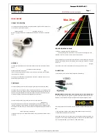
8. Video Signal Output
8.1. Sensor layout
In the GigE Vision Format, only Active Pixel Area is output and the area of dummy and reserved
is not output. If the OB transfer mode is set ON, OB parts of 8 pixels on the top and 16 pixels on
the right are output.
Fig.23
.
Sensor layout and Video output image
Note for output image:
The output area depends on the settings of Pixel Format as well as OB transfer Enable.
The available display image is indicated by ―Width Max‖ and ―Height Max‖ in the control tool.
The following table shows relations mentioned on the above.
OB Transfer Enable =―False‖
OB Transfer Enable =―True‖
Width Max
Height Max
Width Max
Height Max
BayRG8,BayRG10,BayRG12,
BayRG10_Packed,BayRG12_Packed,
Mono8, Mono10, Mono12,
Mono10_Packed,Mono12_Packed
1296
966
1312
970(Note1)
RGB8_Packed,
BGR10V1_Packed, BGR10V2_Packed
1292(Note2)
962(Note2)
-
-
Note1: This is if JAI Partial Scan is set to ―False‖. This will be 966, if JAI Partial Scan is set to ―True‖
Note2: In case of RGB output, 2 pixels each on both sides are not read out.