


en-62
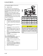
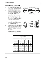
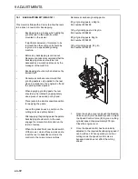
9.13 CUTTING HEIGHT - FLOATING MODE
1.
Assemble the front roller adjuster to holes
number 2 and 4 only of the mower frame.
Do not use hole numbers 1 and 3.
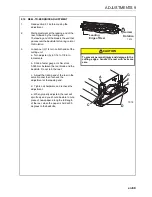
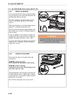
2.
Reposition the rear roller adjusters (F).
a. For cutting heights from 9 to 44 mm
use holes 6 and 8 on the mower frame
and two holes (shown in black) of
adjuster (F) as shown in Figure.
b. For cutting heights greater than 44
mm, disassemble adjuster (F) and turn
the mounting bracket upside down; then
use holes 5 and 7 of the frame and the two
holes (shown in black) of adjuster (F).
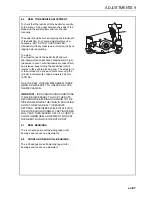
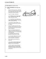
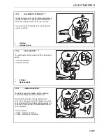
3.
Adjust height gauge (P) to the desired
cutting height. Loosen nut (K) and adjust
screw (L) to obtin dimension (X) then lock
nut (K) against the gauge (P).
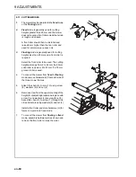
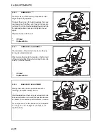
4.
Place one end of the gauge against the front
roller at either side of the reel, and slide the
head of screw (L) over the bedknife.
a. Adjust nut (G ) to lower the rear roller
to the gauge, then tighten nut (E) against
the adjuster.
b. Move the gauge to the other side of
the reel and repeat Steps 4a and 4b.
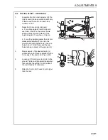
Range of Cut
Safe Operating Range
Grooved Roller
Solid Roller
Front
Rear
9mm - 19mm
9mm - 16mm
R
M
19mm - 32mm
16mm - 28mm
S
M
32mm - 44mm
28mm - 41mm
T
M
44mm - 57mm
41mm - 54mm
U
N
Front Roller
P
Rear Roller
X-Cutting Height
K
L
TK27
1
2
3
4
5
6
7
8
U
T
S
R
N
M
N
M
B
E
F
G
TK20
9 ADJUSTMENTS
Summary of Contents for TR3 EJ Series
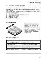
Page 43: ...en 43 OPERATION 7 NOTES ...
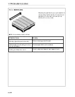
Page 45: ...en 45 MAINTENANCE AND LUBRICATION 8 ...
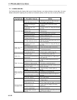
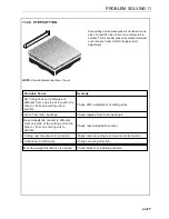
Page 83: ...en 83 PROBLEM SOLVING 11 NOTES ...
Page 84: ...en 84 12 1 HYDRAULIC CIRCUIT 12 SCHEMATICS ...
Page 88: ...en 88 12 3 ELECTRICAL CIRCUIT MAIN 12 SCHEMATICS ...
Page 135: ...cs 43 OBSLUHA 7 POZNÁMKY ...
Page 137: ...cs 45 LUBRIKACE A ÚDRŽBA 8 ...
Page 175: ...cs 83 ODSTRAŇOVÁNÍ PROBLÉMŮ 11 POZNÁMKY ...
Page 176: ...cs 84 12 1 HYDRAULICKÝ OBVOD 12 SCHÉMATA ...
Page 180: ...cs 88 12 3 VEDENÍ ELEKTRICKÉHO OBVODU 12 SCHÉMATA ...