


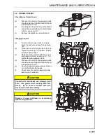


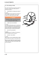

en-56
CUTTING UNITS LMAC194 / 195 / 196 / 197
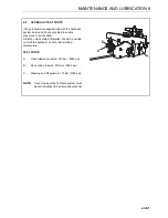
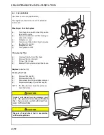
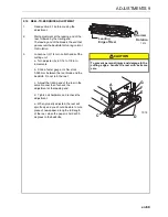
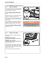
9.3
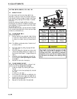
HEIGHT OF CUT
It is important to set the rear roll parallel to the
bedknife in order to achieve the minimum height of
cut setting for the three ranges of height, in the three
sets of mounting housing (D) bolt holes. Positions
'A','B' &'C'.
Setting the minimum height with the mounting
housings (D) in position 'A' will allow minimum height
and parallelism to be achieved in each of the other
two positions 'B' & 'C'.
Once the range has been chosen the actual height
of cut is set by adjusting the front roll only by carriage
screws (F) and locknuts (J).
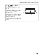
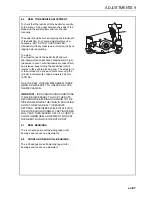
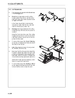
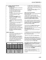
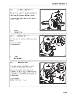
9.4
TO SET REAR ROLL
with a new bedknife
1.
Set the height of cut setting bar (G)as follows:
a. Screw X to 12mm(15/32in) under the head.
b. Screw Y to 6.5mm (1/4in) to screw thread
tip.
Note: The difference between screw X and screw Y
is 5.5mm (7/32in).
2.
Set roll carriage mounting housing(D) bolts
into holes 'A'.
3.
Place the setting bar (G)as shown at one end
of the bottom blade with the screw head X over
the lip and screw thread Y tip against base of
blade.
4.
Adjust the roll to the setting bar (G) with the
two locknuts(H)
holding setting bar screws
in contact.
5.
Repeat for other end of bedknife.
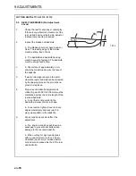
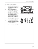
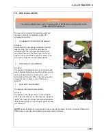
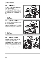
9.5
TO SET HEIGHT OF CUT
Chose the range of height in which cutting is to be
carried out and then
adjust front roll only.
1.
Preset the height of cut setting bar (G)as
follows:
a. Screw X to the required height of cut under
the head.
b. Screw Y is not used.
2.
At one end of the bedknife lay setting bar (G)
on rear roll with screw head over bedknife lip.
3.
Adjust front roll to the setting bar by means of
the two front locknuts (J).
4.
Repeat for the other end of the bedknife.
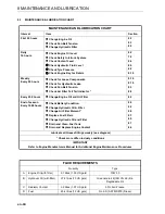
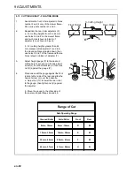
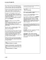
Height of Cut
Range
Minimum
Height of Cut
Maximum
Height of Cut
Holes 'A'
12.0mm
19.0mm
Holes 'B'
19.0mm
35.0mm
Holes 'C'
27.0mm
47.0mm
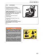
CAUTION
The height of cut range for each set of holes
takes into account the requirement of the
cutting unit to float. Increasing the maximum
height of cut in any of the hole setting ranges
could restrict the ability of the cutting unit to
float.
9 ADJUSTMENTS
Summary of Contents for TR3 EJ Series
Page 43: ...en 43 OPERATION 7 NOTES ...
Page 45: ...en 45 MAINTENANCE AND LUBRICATION 8 ...
Page 83: ...en 83 PROBLEM SOLVING 11 NOTES ...
Page 84: ...en 84 12 1 HYDRAULIC CIRCUIT 12 SCHEMATICS ...
Page 88: ...en 88 12 3 ELECTRICAL CIRCUIT MAIN 12 SCHEMATICS ...
Page 135: ...cs 43 OBSLUHA 7 POZNÁMKY ...
Page 137: ...cs 45 LUBRIKACE A ÚDRŽBA 8 ...
Page 175: ...cs 83 ODSTRAŇOVÁNÍ PROBLÉMŮ 11 POZNÁMKY ...
Page 176: ...cs 84 12 1 HYDRAULICKÝ OBVOD 12 SCHÉMATA ...
Page 180: ...cs 88 12 3 VEDENÍ ELEKTRICKÉHO OBVODU 12 SCHÉMATA ...