


en-61
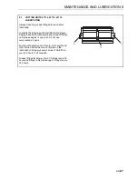
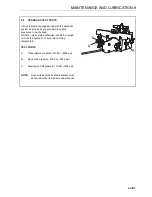
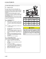
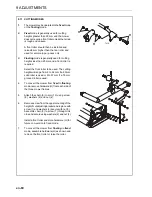
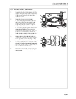
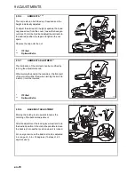
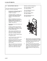
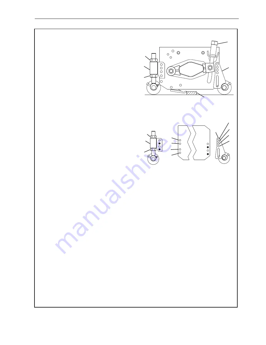
9.12 CUTTING HEIGHT - FIXED MODE
1.
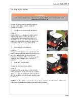
Assemble the front roller adjuster (B) (If a
roller is used) to holes number 2 and 4 only
of the mower frame. Do not use holes
number 1 and 3.
2.
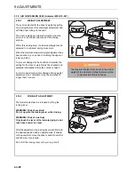
Reposition the rear roller adjuster.
a. For cutting heights from 9 to 44 mm,
use holes 6 and 8 on the mower frame
and two holes (shown in black) of the
height adjuster (F) as shown in Figure.
b. For cutting heights greater than 44 mm
disassemble adjuster (F) and turn the
mounting bracket upside down; then use
holes 5 and 7 of the frame and the two
holes (shown in black) of the adjuster (F).
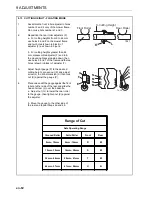
3.
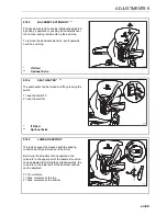
Place spacers of the desired height (J)
under each end of the reel, adjacent to the
front edge of the bed-knife. (Figure 4R)
4.
Loosen nut (G) and lower rear roller to the
ground. Tighten nut (E) against the adjuster
then recheck the setting on both sides of
the reel. Readjust if necessary.
5.
Raise the front roller (if used) 6 mm higher
than the rear.
TK25
G
J
F
E
A
B
1
2
3
4
5
6
7
8
U
T
S
R
N
M
N
M
B
E
F
G
TK20
ADJUSTMENTS 9
Summary of Contents for TR3 EJ Series
Page 43: ...en 43 OPERATION 7 NOTES ...
Page 45: ...en 45 MAINTENANCE AND LUBRICATION 8 ...
Page 83: ...en 83 PROBLEM SOLVING 11 NOTES ...
Page 84: ...en 84 12 1 HYDRAULIC CIRCUIT 12 SCHEMATICS ...
Page 88: ...en 88 12 3 ELECTRICAL CIRCUIT MAIN 12 SCHEMATICS ...
Page 135: ...cs 43 OBSLUHA 7 POZNÁMKY ...
Page 137: ...cs 45 LUBRIKACE A ÚDRŽBA 8 ...
Page 175: ...cs 83 ODSTRAŇOVÁNÍ PROBLÉMŮ 11 POZNÁMKY ...
Page 176: ...cs 84 12 1 HYDRAULICKÝ OBVOD 12 SCHÉMATA ...
Page 180: ...cs 88 12 3 VEDENÍ ELEKTRICKÉHO OBVODU 12 SCHÉMATA ...