SERVICE MANUAL FOR SXG323&326
38
(7) Make sure that fuel ejects from the delivery
holder. Turn the crankshaft slowly in correct
direction (clockwise viewed from the fan) until
fuel ejection stops. The injection timing is just
before fuel ejection stops.
• When fuel ejection stops, the injection timing
point is passed. Turn the crankshaft in reverse
and repeat operation (6).
• Even when the injection timing point is passed,
there is no sign of fuel ejection stopping. The
point is BTDC in exhaust stroke. Turn the crank-
shaft fully by 360" and start operation.
• As a criterion of
just before fuel stops," use
the time to take to refill the fuel in the end of the
delivery holder after blowing it off. When it
takes 1 to 2 seconds to refill, it is the fuel injec-
tion timing point.
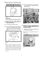
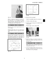
(8) Check to see the timing mark on the flywheel or
the crankshaft pulley is aligned as shown in
3.2. Adjustment of valve clearance.
For reference:
The crank angle 1
°
is about 1mm on the crank-
shaft pulley and about 2.5 mm on the flywheel.
(9) Turn the key switch to OFF and close the fuel
cock.
(10)After checking to see the fuel injection timing is
correct, remove the delivery holder and install
the delivery spring and stopper. Then re-tighten
the delivery holder to the specified torque.
(11)Install the injection pipe and tighten the nut to
the specified torque.
Note:
-Supply fuel only when fuel injection timing is
measured (only for operation 6)].
-It is impossible to measure the fuel injection tim-
ing by turning the crankshaft in reverse (counter-
clockwise viewed from the fan).
-During this operation, be sure to keep dust out of
the fuel system.
• Adjustment of injection timing
When the injection timing is improper, it should
be corrected.
The injection timing can be adjusted by chang-
ing the distance between the camshaft and
pump-mounting surface with shims.
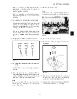
a. Remove the injection pump cover.
b. Remove
t
he control link and starting spring from
the control rack.
c. Remove the injection pump.
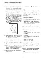
-Shimming
Available adjusting shims: 0.1, 0.2, 0.3, 0.4 and
0.5 mm thick.
For reference:
Injection timing shift with 0.1 mm thick shim-
ming by crank angle:
Sh0.1 mm 1
°
delay
Shimming -0.1 mm 1
°
advance
d. Install the injection pump.
e. Confirm that the injection timing is proper by the
operation mentioned above. Until the proper fuel
injection timing is attained, repeat steps from c. to
e.
f. Install the control link and starting spring on the
control rack and then the injection pump cover.
Note:
During this operation, be careful to keep dust out
of the fuel system.
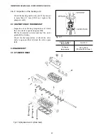
4IGHTENING TORQUE
KGF
・
M
&IG
Summary of Contents for SXG323
Page 1: ...LAWN MOWERS MOWER DECKS COLLECTORS SCMB48 SCMA54 SBC550X 600X ...
Page 5: ......
Page 11: ...SERVICE MANUAL FOR SXG323 326 10 ...
Page 14: ...CHAPTER 1 GENERAL INFORMATION 13 1 3 EXTERIOR VIEW Fig 1 4 ...
Page 17: ...SERVICE MANUAL FOR SXG323 326 16 ...
Page 33: ...SERVICE MANUAL FOR SXG323 326 32 ...
Page 51: ...SERVICE MANUAL FOR SXG323 326 50 3 3 CYLINDER BLOCK 3 3 1 EXPLODED VIEW Fig 4 55 ...
Page 67: ...SERVICE MANUAL FOR SXG323 326 66 ...
Page 70: ...CHAPTER 5 LUBRICATION SYSTEM 69 5 1 4 EXPLODED VIEW OF OIL PUMP Fig 5 4 ...
Page 73: ...SERVICE MANUAL FOR SXG323 326 72 ...
Page 89: ...SERVICE MANUAL FOR SXG323 326 88 42 3 33 Fig 8 3 2 2 7 2 6 3 TYPE Fig 8 4 ...
Page 93: ...SERVICE MANUAL FOR SXG323 326 92 ...
Page 97: ...SERVICE MANUAL FOR SXG323 326 96 2 OPERATING DIAGRAM OF HST Fig 10 2 ...
Page 99: ...SERVICE MANUAL FOR SXG323 326 98 Fig 10 5 Fig 10 6 ...
Page 100: ...CHAPTER 10 HYDROSTATIC TRANSMISSION 99 10 Fig 10 7 ...
Page 101: ...SERVICE MANUAL FOR SXG323 326 100 Fig 10 8 4 DISASSEMBLY AND REASSEMBLY ...
Page 102: ...CHAPTER 10 HYDROSTATIC TRANSMISSION 101 10 4 3 ...
Page 103: ...SERVICE MANUAL FOR SXG323 326 102 ...
Page 107: ...SERVICE MANUAL FOR SXG323 326 106 4 5 CRITERIA FOR REPLACING WORN PARTS ...
Page 117: ...SERVICE MANUAL FOR SXG323 326 116 ...
Page 124: ...CHAPTER 12 POWER STEERING SYSTEM 123 12 3 MAJOR TROUBLES AND CAUSES AND COUNTERMEASURES ...
Page 125: ...SERVICE MANUAL FOR SXG323 326 124 ...
Page 126: ...CHAPTER 12 POWER STEERING SYSTEM 125 12 ...
Page 127: ...SERVICE MANUAL FOR SXG323 326 126 ...
Page 130: ...CHAPTER 13 ELECTRICAL ACCESSORIES 129 13 2 WIRING DIAGRAM E TYPE Fig 13 12 ...
Page 131: ...SERVICE MANUAL FOR SXG323 326 130 3 WIRING DIAGRAM GE TYPE Fig 13 13 ...
Page 132: ...CHAPTER 13 ELECTRICAL ACCESSORIES 131 13 Fig 13 14 4 STARTER ...
Page 140: ...CHAPTER 13 ELECTRICAL ACCESSORIES 139 13 Fig 13 48 Fig 13 47 ...
Page 149: ......
Page 151: ...SERVICE MANUAL FOR SXG323 326 4 ...
Page 152: ...CHAPTER 1 FOR SAFETY LABELS 5 1 SAFETY LABELS SCMB48 54 CHAPTER 1 FOR SAFETY LABELS ...
Page 163: ...SERVICE MANUAL FOR SXG323 326 16 ...
Page 171: ...SERVICE MANUAL FOR SXG323 326 24 ...
Page 173: ...SERVICE MANUAL FOR SXG323 326 26 3 Gear box left hand ...
Page 175: ...SERVICE MANUAL FOR SXG323 326 28 SCMB48 54 Front Belt and Belt tension Blade and Blade hub ...
Page 183: ......
Page 185: ...SERVICE MANUAL FOR SXG323 326 4 ...
Page 188: ...CHAPTER 2 SPECIFICATIONS 7 2 SPECIFICATIONS CHAPTER 2 SPECIFICATIONS ...
Page 189: ...SERVICE MANUAL FOR SXG323 326 8 ...
Page 191: ...SERVICE MANUAL FOR SXG323 326 10 ...
Page 195: ...SERVICE MANUAL FOR SXG323 326 14 ...
Page 227: ...SERVICE MANUAL FOR SXG323 326 46 ...
Page 229: ...SERVICE MANUAL FOR SXG323 326 48 ...

