SERVICE MANUAL FOR SXG323&326
18
c. O-rings
• O-rings should be coated with grease before
installing.
• Installed O-rings should have no slack or twist.
• Installed O-rings should maintain proper air
tightness.
d. Snap-rings
• Snap-ring installers should be designed so as not
to permanently deform the snap-rings.
• Installed snap-rings should be seated securely in
the groove.
• Be careful not to overload the snap-ring to the
extent that it is permanently deformed.
•How to install the snap-ring:
When installing a snap-ring, install it as shown in
the figure with its round edge side turned toward
the part to be retained. This round edge is formed
when the snap-ring is pressed out.
Fig. 2-1
e. Spring (roll) pins
• Spring pins should be driven in properly and
tightly.
• Spring pins should be installed so that their
seams should face the direction from which the
load is applied.
Fig. 2-2
• The roll pins installed in the transmission or other
parts where much force is applied should be retained
with wire.
f. Cotter pins(Split pin)
•When installed, cotter pins should be bent securely at
the ends as shown in the figure.
Fig. 2-3
g. Bolts and nuts
• Special bolts are installed at several locations, so be
sure not to interchange them other bolts.
• Bolts and nuts should be tightened to their specified
torque with a torque wrench.
• When locking the bolts or nuts with wire or a lock
washer, be sure to wind the wire paying sufficient
attention to its winding direction and bend the lock
washer for secure locking.
• When locking bolts and nuts with an adhesive, apply
the adhesive on the thread and tighten securely.
•Apply an adhesive (THREE BOND TB1104) to parts
through which there is any possibility of oil leaks,
such as stud bolts and tapped-through parts.
• Each lock nut must be tightened securely.
• When tightening bolts and nuts, refer to the tightening
torque table.
h. After installation, each grease fitting should
be filled with grease.
• When installing grease fittings of types B and C, be
sure to turn the fitting tips in a direction that will
provide easy access for a grease gun.
Summary of Contents for SXG323
Page 1: ...LAWN MOWERS MOWER DECKS COLLECTORS SCMB48 SCMA54 SBC550X 600X ...
Page 5: ......
Page 11: ...SERVICE MANUAL FOR SXG323 326 10 ...
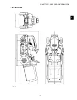
Page 14: ...CHAPTER 1 GENERAL INFORMATION 13 1 3 EXTERIOR VIEW Fig 1 4 ...
Page 17: ...SERVICE MANUAL FOR SXG323 326 16 ...
Page 33: ...SERVICE MANUAL FOR SXG323 326 32 ...
Page 51: ...SERVICE MANUAL FOR SXG323 326 50 3 3 CYLINDER BLOCK 3 3 1 EXPLODED VIEW Fig 4 55 ...
Page 67: ...SERVICE MANUAL FOR SXG323 326 66 ...
Page 70: ...CHAPTER 5 LUBRICATION SYSTEM 69 5 1 4 EXPLODED VIEW OF OIL PUMP Fig 5 4 ...
Page 73: ...SERVICE MANUAL FOR SXG323 326 72 ...
Page 89: ...SERVICE MANUAL FOR SXG323 326 88 42 3 33 Fig 8 3 2 2 7 2 6 3 TYPE Fig 8 4 ...
Page 93: ...SERVICE MANUAL FOR SXG323 326 92 ...
Page 97: ...SERVICE MANUAL FOR SXG323 326 96 2 OPERATING DIAGRAM OF HST Fig 10 2 ...
Page 99: ...SERVICE MANUAL FOR SXG323 326 98 Fig 10 5 Fig 10 6 ...
Page 100: ...CHAPTER 10 HYDROSTATIC TRANSMISSION 99 10 Fig 10 7 ...
Page 101: ...SERVICE MANUAL FOR SXG323 326 100 Fig 10 8 4 DISASSEMBLY AND REASSEMBLY ...
Page 102: ...CHAPTER 10 HYDROSTATIC TRANSMISSION 101 10 4 3 ...
Page 103: ...SERVICE MANUAL FOR SXG323 326 102 ...
Page 107: ...SERVICE MANUAL FOR SXG323 326 106 4 5 CRITERIA FOR REPLACING WORN PARTS ...
Page 117: ...SERVICE MANUAL FOR SXG323 326 116 ...
Page 124: ...CHAPTER 12 POWER STEERING SYSTEM 123 12 3 MAJOR TROUBLES AND CAUSES AND COUNTERMEASURES ...
Page 125: ...SERVICE MANUAL FOR SXG323 326 124 ...
Page 126: ...CHAPTER 12 POWER STEERING SYSTEM 125 12 ...
Page 127: ...SERVICE MANUAL FOR SXG323 326 126 ...
Page 130: ...CHAPTER 13 ELECTRICAL ACCESSORIES 129 13 2 WIRING DIAGRAM E TYPE Fig 13 12 ...
Page 131: ...SERVICE MANUAL FOR SXG323 326 130 3 WIRING DIAGRAM GE TYPE Fig 13 13 ...
Page 132: ...CHAPTER 13 ELECTRICAL ACCESSORIES 131 13 Fig 13 14 4 STARTER ...
Page 140: ...CHAPTER 13 ELECTRICAL ACCESSORIES 139 13 Fig 13 48 Fig 13 47 ...
Page 149: ......
Page 151: ...SERVICE MANUAL FOR SXG323 326 4 ...
Page 152: ...CHAPTER 1 FOR SAFETY LABELS 5 1 SAFETY LABELS SCMB48 54 CHAPTER 1 FOR SAFETY LABELS ...
Page 163: ...SERVICE MANUAL FOR SXG323 326 16 ...
Page 171: ...SERVICE MANUAL FOR SXG323 326 24 ...
Page 173: ...SERVICE MANUAL FOR SXG323 326 26 3 Gear box left hand ...
Page 175: ...SERVICE MANUAL FOR SXG323 326 28 SCMB48 54 Front Belt and Belt tension Blade and Blade hub ...
Page 183: ......
Page 185: ...SERVICE MANUAL FOR SXG323 326 4 ...
Page 188: ...CHAPTER 2 SPECIFICATIONS 7 2 SPECIFICATIONS CHAPTER 2 SPECIFICATIONS ...
Page 189: ...SERVICE MANUAL FOR SXG323 326 8 ...
Page 191: ...SERVICE MANUAL FOR SXG323 326 10 ...
Page 195: ...SERVICE MANUAL FOR SXG323 326 14 ...
Page 227: ...SERVICE MANUAL FOR SXG323 326 46 ...
Page 229: ...SERVICE MANUAL FOR SXG323 326 48 ...


