SERVICE MANUAL FOR SXG323&326
114
acceralate to the specified speed.
(2) OIL TEMPERATURE
It is a very important factor at what temperature
a hydraulic system operates. High operating tem-
peraure will cause working oil to deteriorate
faster, that is, oil is oxidized faster. On the other
hand excessively low operating temperature in-
creases oil viscosity resulting in poor mechani-
cal efficiency of the HST.
Consequently abide by the following items:
a. When starting the machine at 10
°C
or colder
temperature, wait until oil temperature becomes
higher than 10
°C
by warm-up operation or us-
ing an oil heater. Then start operation.
b. Normal operating temperature: 20
°C
to 60
°C
c. Maximum operating temperature
The maximum operating temperature should be
80
°C
. This limit is determined form the viscoci-
ty, oxidation-proof property of working oil and
deterioration of O-rings and oil seals.
Consequently operation at higher than 80
°C
will
shorten the service life of the HST and working
oil.
(3) PERIODICAL INSPECTION AND CHANG-
ING INTERVALS OF WORKING OIL
As the system operates, deposits like sludge ac-
cumulate within circuits and oil tank and work-
ing oil deteriorates, which will prevent the sys-
tem from smooth operation in the end.
Consequently working oil should be checked
periodically to replace it timely with new one.
As it is very difficult to judge how oil has dete-
riorated visually, a rule of thumb is given below.
Normally the oil should be replaced after the
intial 50 hours of operaton and then every year
(before the new season begins) when the
machine is used for less than 250 hours or every
250 hours of operation.
As water and sludge will be deposited in the cir-
cuits and oil tank when replacing the working
oil, the whole system should be flushed clean
before filling it with new oil
5. ADJUSTMENT OF HIST
Warning:
After a long time of use, the neutral position of
the HST unit can shift, which will cause various
troubles such as difficulty in stopping the lawn
mower, changing over between forward travel
and reverse travel, etc., which is very dangerous.
Important:
• When the HST unit is out of order, ask your deal-
ers to repair it.
• The adjustment of the neutral position of the HST
unit should be done by your dealers.
When there is no alternative but for the user to adjust
it, follow the next instructions:
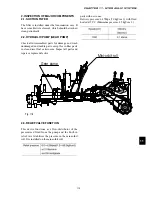
The neutral arm of the HST unit is located around
the centre under the step.
With this arm the neutral position can be adjusted.
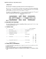
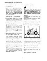
Fig. 10-45
(1) Lawn mower
(3) Front wheel
(2) Tyre chocks
(4) Rear wheel
a. Place the lawn mower on level, hard ground Put
tyre chocks in the positions a little apart from the
front wheels and rear wheels as shown in the fig-
ure.
b. Shift the PTO lever to the OFF position (
N
).
c. Stop the engine and remove the starter key.
d. Apply the parking brakes (UGE) or locking brake
(UE).
e. Loosen the lock nut of the adjust rod.
Summary of Contents for SXG323
Page 1: ...LAWN MOWERS MOWER DECKS COLLECTORS SCMB48 SCMA54 SBC550X 600X ...
Page 5: ......
Page 11: ...SERVICE MANUAL FOR SXG323 326 10 ...
Page 14: ...CHAPTER 1 GENERAL INFORMATION 13 1 3 EXTERIOR VIEW Fig 1 4 ...
Page 17: ...SERVICE MANUAL FOR SXG323 326 16 ...
Page 33: ...SERVICE MANUAL FOR SXG323 326 32 ...
Page 51: ...SERVICE MANUAL FOR SXG323 326 50 3 3 CYLINDER BLOCK 3 3 1 EXPLODED VIEW Fig 4 55 ...
Page 67: ...SERVICE MANUAL FOR SXG323 326 66 ...
Page 70: ...CHAPTER 5 LUBRICATION SYSTEM 69 5 1 4 EXPLODED VIEW OF OIL PUMP Fig 5 4 ...
Page 73: ...SERVICE MANUAL FOR SXG323 326 72 ...
Page 89: ...SERVICE MANUAL FOR SXG323 326 88 42 3 33 Fig 8 3 2 2 7 2 6 3 TYPE Fig 8 4 ...
Page 93: ...SERVICE MANUAL FOR SXG323 326 92 ...
Page 97: ...SERVICE MANUAL FOR SXG323 326 96 2 OPERATING DIAGRAM OF HST Fig 10 2 ...
Page 99: ...SERVICE MANUAL FOR SXG323 326 98 Fig 10 5 Fig 10 6 ...
Page 100: ...CHAPTER 10 HYDROSTATIC TRANSMISSION 99 10 Fig 10 7 ...
Page 101: ...SERVICE MANUAL FOR SXG323 326 100 Fig 10 8 4 DISASSEMBLY AND REASSEMBLY ...
Page 102: ...CHAPTER 10 HYDROSTATIC TRANSMISSION 101 10 4 3 ...
Page 103: ...SERVICE MANUAL FOR SXG323 326 102 ...
Page 107: ...SERVICE MANUAL FOR SXG323 326 106 4 5 CRITERIA FOR REPLACING WORN PARTS ...
Page 117: ...SERVICE MANUAL FOR SXG323 326 116 ...
Page 124: ...CHAPTER 12 POWER STEERING SYSTEM 123 12 3 MAJOR TROUBLES AND CAUSES AND COUNTERMEASURES ...
Page 125: ...SERVICE MANUAL FOR SXG323 326 124 ...
Page 126: ...CHAPTER 12 POWER STEERING SYSTEM 125 12 ...
Page 127: ...SERVICE MANUAL FOR SXG323 326 126 ...
Page 130: ...CHAPTER 13 ELECTRICAL ACCESSORIES 129 13 2 WIRING DIAGRAM E TYPE Fig 13 12 ...
Page 131: ...SERVICE MANUAL FOR SXG323 326 130 3 WIRING DIAGRAM GE TYPE Fig 13 13 ...
Page 132: ...CHAPTER 13 ELECTRICAL ACCESSORIES 131 13 Fig 13 14 4 STARTER ...
Page 140: ...CHAPTER 13 ELECTRICAL ACCESSORIES 139 13 Fig 13 48 Fig 13 47 ...
Page 149: ......
Page 151: ...SERVICE MANUAL FOR SXG323 326 4 ...
Page 152: ...CHAPTER 1 FOR SAFETY LABELS 5 1 SAFETY LABELS SCMB48 54 CHAPTER 1 FOR SAFETY LABELS ...
Page 163: ...SERVICE MANUAL FOR SXG323 326 16 ...
Page 171: ...SERVICE MANUAL FOR SXG323 326 24 ...
Page 173: ...SERVICE MANUAL FOR SXG323 326 26 3 Gear box left hand ...
Page 175: ...SERVICE MANUAL FOR SXG323 326 28 SCMB48 54 Front Belt and Belt tension Blade and Blade hub ...
Page 183: ......
Page 185: ...SERVICE MANUAL FOR SXG323 326 4 ...
Page 188: ...CHAPTER 2 SPECIFICATIONS 7 2 SPECIFICATIONS CHAPTER 2 SPECIFICATIONS ...
Page 189: ...SERVICE MANUAL FOR SXG323 326 8 ...
Page 191: ...SERVICE MANUAL FOR SXG323 326 10 ...
Page 195: ...SERVICE MANUAL FOR SXG323 326 14 ...
Page 227: ...SERVICE MANUAL FOR SXG323 326 46 ...
Page 229: ...SERVICE MANUAL FOR SXG323 326 48 ...

