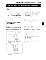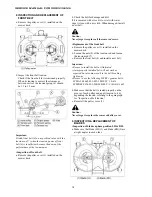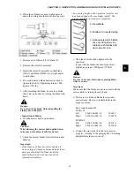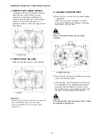
CHAPTER 4. MOWER OPERATION
13
4
Warning:
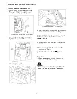
· As soon as the PTO lever is shifted to the ON
(
) Position, the mower blades start rotating
and eject cut grass or stones through the
discharge opening. Consequently, before
operating the PTO lever make sure that there
is no people, animals, or physical properties
like buildings cars, etc. within a range where
ejected grass or stones may reach.
· The mower blades should be turned only on
turf or grassland with the mower deck
lowered.
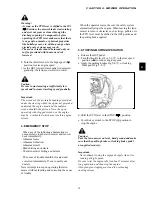
h. Turn the throttle lever to the high speed (
r
)
position to raise engine speed.
i. As the HST forward travel pedal is depressed
gradually, the lawn mower starts to travel.
Caution:
Be sure to start mowing at sufficiently low
speeds and increase traveling speed gradually.
Important:
The screens of the air-intake openings provided
under the steering wheel, the upper net provided
underside the engine hood and the radiator
screen should be kept clean. Never keep on
operating with clogged screens, or the engine
may be overheated, which may result in engine
seizure.
4. EMERGENCY STOP
· When any of the following abnormalities is
encountered, stop the lawn mower and mower
deck immediately.
- Abnormal noise
- Abnormal vibration
- Abnormal smell
- Blade hitting an obstacle
- The lawn mower hitting an obstacle
· The cause of trouble should be located and
corrected immediately. If not, consult your
dealers.
Never attempt to keep on operating the lawn
mower without locating and correcting the cause
of trouble.
· When the operator leaves the seat, the safety system
automatically stops the engine. When leaving the lawn
mower to remove obstacles such as twigs, pebbles, etc.
the PTO lever must be shifted to the OFF position and
the parking brake applied.
5. STOPPING MOWING OPERATION
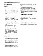
a. Release the HST pedal.
b. Turn the throttle lever Fig.5-3-
䷵
to the low speed
position (
t
) to reduce engine speeds.
c. Apply the parking brakes Fig.5-4-
䷵
, or locking
brake pedal Fig.5-5-
䷵
.
d. Shift the PTO lever to the STOP (
) position
e. Turn the key switch to the STOP (
$
) position to
stop the engine
Caution:
Park the lawn mower on level, hard ground and make
sure that the parking brakes or locking brake pedal
are applied securely.
Important:
· Never attempt to stop the engine abruptly when it is
running at high speeds.
Be sure to let the engine idle for about 5 minutes after
long operation and then stop the engine.
Abrupt engine stopping may lead to overheating
causing seizure.
Summary of Contents for SXG323
Page 1: ...LAWN MOWERS MOWER DECKS COLLECTORS SCMB48 SCMA54 SBC550X 600X ...
Page 5: ......
Page 11: ...SERVICE MANUAL FOR SXG323 326 10 ...
Page 14: ...CHAPTER 1 GENERAL INFORMATION 13 1 3 EXTERIOR VIEW Fig 1 4 ...
Page 17: ...SERVICE MANUAL FOR SXG323 326 16 ...
Page 33: ...SERVICE MANUAL FOR SXG323 326 32 ...
Page 51: ...SERVICE MANUAL FOR SXG323 326 50 3 3 CYLINDER BLOCK 3 3 1 EXPLODED VIEW Fig 4 55 ...
Page 67: ...SERVICE MANUAL FOR SXG323 326 66 ...
Page 70: ...CHAPTER 5 LUBRICATION SYSTEM 69 5 1 4 EXPLODED VIEW OF OIL PUMP Fig 5 4 ...
Page 73: ...SERVICE MANUAL FOR SXG323 326 72 ...
Page 89: ...SERVICE MANUAL FOR SXG323 326 88 42 3 33 Fig 8 3 2 2 7 2 6 3 TYPE Fig 8 4 ...
Page 93: ...SERVICE MANUAL FOR SXG323 326 92 ...
Page 97: ...SERVICE MANUAL FOR SXG323 326 96 2 OPERATING DIAGRAM OF HST Fig 10 2 ...
Page 99: ...SERVICE MANUAL FOR SXG323 326 98 Fig 10 5 Fig 10 6 ...
Page 100: ...CHAPTER 10 HYDROSTATIC TRANSMISSION 99 10 Fig 10 7 ...
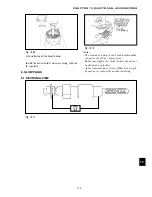
Page 101: ...SERVICE MANUAL FOR SXG323 326 100 Fig 10 8 4 DISASSEMBLY AND REASSEMBLY ...
Page 102: ...CHAPTER 10 HYDROSTATIC TRANSMISSION 101 10 4 3 ...
Page 103: ...SERVICE MANUAL FOR SXG323 326 102 ...
Page 107: ...SERVICE MANUAL FOR SXG323 326 106 4 5 CRITERIA FOR REPLACING WORN PARTS ...
Page 117: ...SERVICE MANUAL FOR SXG323 326 116 ...
Page 124: ...CHAPTER 12 POWER STEERING SYSTEM 123 12 3 MAJOR TROUBLES AND CAUSES AND COUNTERMEASURES ...
Page 125: ...SERVICE MANUAL FOR SXG323 326 124 ...
Page 126: ...CHAPTER 12 POWER STEERING SYSTEM 125 12 ...
Page 127: ...SERVICE MANUAL FOR SXG323 326 126 ...
Page 130: ...CHAPTER 13 ELECTRICAL ACCESSORIES 129 13 2 WIRING DIAGRAM E TYPE Fig 13 12 ...
Page 131: ...SERVICE MANUAL FOR SXG323 326 130 3 WIRING DIAGRAM GE TYPE Fig 13 13 ...
Page 132: ...CHAPTER 13 ELECTRICAL ACCESSORIES 131 13 Fig 13 14 4 STARTER ...
Page 140: ...CHAPTER 13 ELECTRICAL ACCESSORIES 139 13 Fig 13 48 Fig 13 47 ...
Page 149: ......
Page 151: ...SERVICE MANUAL FOR SXG323 326 4 ...
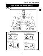
Page 152: ...CHAPTER 1 FOR SAFETY LABELS 5 1 SAFETY LABELS SCMB48 54 CHAPTER 1 FOR SAFETY LABELS ...
Page 163: ...SERVICE MANUAL FOR SXG323 326 16 ...
Page 171: ...SERVICE MANUAL FOR SXG323 326 24 ...
Page 173: ...SERVICE MANUAL FOR SXG323 326 26 3 Gear box left hand ...
Page 175: ...SERVICE MANUAL FOR SXG323 326 28 SCMB48 54 Front Belt and Belt tension Blade and Blade hub ...
Page 183: ......
Page 185: ...SERVICE MANUAL FOR SXG323 326 4 ...
Page 188: ...CHAPTER 2 SPECIFICATIONS 7 2 SPECIFICATIONS CHAPTER 2 SPECIFICATIONS ...
Page 189: ...SERVICE MANUAL FOR SXG323 326 8 ...
Page 191: ...SERVICE MANUAL FOR SXG323 326 10 ...
Page 195: ...SERVICE MANUAL FOR SXG323 326 14 ...
Page 227: ...SERVICE MANUAL FOR SXG323 326 46 ...
Page 229: ...SERVICE MANUAL FOR SXG323 326 48 ...

