CHAPTER 2. DISASSEMBLY OF MAJOR COMPONENTS
17
2
1. GENERAL PRECAUTIONS FOR SEPARATION AND REINSTALLATION
1.1. BEFORE OPERATION
a. Always be safety-conscious in selecting clothes
to wear and suitable tools to use.
b. Before disassembly, be sure that you familiarize
yourself with the assembled condition for
subsequent reference in reassembly.
c. Keep parts and tools in proper order during
operations.
d. When servicing electrically live parts, be sure to
disconnect the negative battery terminal.
e. To prevent oil or water leaks, use the liquid
gasket as required.
f. When reassembling disassembled parts, discard
used gaskets, O-rings, or oil seals and install new
ones.
g. When lifting up only the front or rear part of the
tractor, be sure to wedge the grounded wheels.
h. When the tractor is jacked up, be sure to support
the entire tractor with something like a stand.
Lifting it up with a jack only is a dangerously
unstable procedure.
i. When replacing parts, use authorized, genuine
ISEKI parts only. ISEKI assumes no responsibility
for accidents, operating problems or dam-age
caused by the use of imitation parts. Also, the use
of unauthorized parts will result in relatively poor
machine performance.
1.2. PRECAUTIONS TO BE FOLLOWED WHEN
INSTALLING COMMON PARTS
a. Roller or ball bearings
• When a bearing is fitted in by the outer race, use an
installer which is specially designed to push only the
outer race and vice versa.
• The installer must be designed to install the bearing
on the shaft in a parallel position.
•When installing a bearing which appears the same on
both sides, install it so that the face which has the
identification number faces in a direction for easy
visual identification. All the bearings which are to be
installed in the transmission case should be placed so
that their identification number faces outward.
• If a shaft or a hole where a bearing is to be installed
has a stopper, the bearing should be pushed in
completely until it is seated against the stopper.
• Installed bearings should turn smoothly.
b. Oil seals
• Oil seal installer should be designed so as not to
deform the oil seals.
• During installation, be careful not to damage the lips,
and assure that it is pushed in parallel to the shaft or
hole.
• When oil seals are installed, there should be no
turnover of the lips nor dislocation of the springs.
• When a multi-lip seal is installed, the grooves
between lips should be filled with grease, not
adhesive.
• Use a lithium-based grease.
• There should be no oil or water leaks through the
installed soil seals.
CHAPTER 2. DISASSEMBLY OF MAJOR COMPONENTS
Summary of Contents for SXG323
Page 1: ...LAWN MOWERS MOWER DECKS COLLECTORS SCMB48 SCMA54 SBC550X 600X ...
Page 5: ......
Page 11: ...SERVICE MANUAL FOR SXG323 326 10 ...
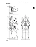
Page 14: ...CHAPTER 1 GENERAL INFORMATION 13 1 3 EXTERIOR VIEW Fig 1 4 ...
Page 17: ...SERVICE MANUAL FOR SXG323 326 16 ...
Page 33: ...SERVICE MANUAL FOR SXG323 326 32 ...
Page 51: ...SERVICE MANUAL FOR SXG323 326 50 3 3 CYLINDER BLOCK 3 3 1 EXPLODED VIEW Fig 4 55 ...
Page 67: ...SERVICE MANUAL FOR SXG323 326 66 ...
Page 70: ...CHAPTER 5 LUBRICATION SYSTEM 69 5 1 4 EXPLODED VIEW OF OIL PUMP Fig 5 4 ...
Page 73: ...SERVICE MANUAL FOR SXG323 326 72 ...
Page 89: ...SERVICE MANUAL FOR SXG323 326 88 42 3 33 Fig 8 3 2 2 7 2 6 3 TYPE Fig 8 4 ...
Page 93: ...SERVICE MANUAL FOR SXG323 326 92 ...
Page 97: ...SERVICE MANUAL FOR SXG323 326 96 2 OPERATING DIAGRAM OF HST Fig 10 2 ...
Page 99: ...SERVICE MANUAL FOR SXG323 326 98 Fig 10 5 Fig 10 6 ...
Page 100: ...CHAPTER 10 HYDROSTATIC TRANSMISSION 99 10 Fig 10 7 ...
Page 101: ...SERVICE MANUAL FOR SXG323 326 100 Fig 10 8 4 DISASSEMBLY AND REASSEMBLY ...
Page 102: ...CHAPTER 10 HYDROSTATIC TRANSMISSION 101 10 4 3 ...
Page 103: ...SERVICE MANUAL FOR SXG323 326 102 ...
Page 107: ...SERVICE MANUAL FOR SXG323 326 106 4 5 CRITERIA FOR REPLACING WORN PARTS ...
Page 117: ...SERVICE MANUAL FOR SXG323 326 116 ...
Page 124: ...CHAPTER 12 POWER STEERING SYSTEM 123 12 3 MAJOR TROUBLES AND CAUSES AND COUNTERMEASURES ...
Page 125: ...SERVICE MANUAL FOR SXG323 326 124 ...
Page 126: ...CHAPTER 12 POWER STEERING SYSTEM 125 12 ...
Page 127: ...SERVICE MANUAL FOR SXG323 326 126 ...
Page 130: ...CHAPTER 13 ELECTRICAL ACCESSORIES 129 13 2 WIRING DIAGRAM E TYPE Fig 13 12 ...
Page 131: ...SERVICE MANUAL FOR SXG323 326 130 3 WIRING DIAGRAM GE TYPE Fig 13 13 ...
Page 132: ...CHAPTER 13 ELECTRICAL ACCESSORIES 131 13 Fig 13 14 4 STARTER ...
Page 140: ...CHAPTER 13 ELECTRICAL ACCESSORIES 139 13 Fig 13 48 Fig 13 47 ...
Page 149: ......
Page 151: ...SERVICE MANUAL FOR SXG323 326 4 ...
Page 152: ...CHAPTER 1 FOR SAFETY LABELS 5 1 SAFETY LABELS SCMB48 54 CHAPTER 1 FOR SAFETY LABELS ...
Page 163: ...SERVICE MANUAL FOR SXG323 326 16 ...
Page 171: ...SERVICE MANUAL FOR SXG323 326 24 ...
Page 173: ...SERVICE MANUAL FOR SXG323 326 26 3 Gear box left hand ...
Page 175: ...SERVICE MANUAL FOR SXG323 326 28 SCMB48 54 Front Belt and Belt tension Blade and Blade hub ...
Page 183: ......
Page 185: ...SERVICE MANUAL FOR SXG323 326 4 ...
Page 188: ...CHAPTER 2 SPECIFICATIONS 7 2 SPECIFICATIONS CHAPTER 2 SPECIFICATIONS ...
Page 189: ...SERVICE MANUAL FOR SXG323 326 8 ...
Page 191: ...SERVICE MANUAL FOR SXG323 326 10 ...
Page 195: ...SERVICE MANUAL FOR SXG323 326 14 ...
Page 227: ...SERVICE MANUAL FOR SXG323 326 46 ...
Page 229: ...SERVICE MANUAL FOR SXG323 326 48 ...

