


vi
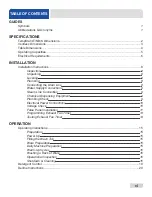
TABLE OF CONTENTS
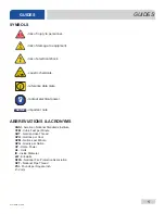
GUIDES
Symbols
1
Abbreviations & Acronyms
1
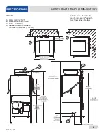
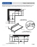
SPECIFICATIONS
TempStar/LT/NB/S Dimensions .................................................................................................. 2
Ventless Dimensions
.................................................................................................................. 3
Table Dimensions ....................................................................................................................... 4
Operating Capacities .................................................................................................................. 5
Electrical Requirements ............................................................................................................. 6
INSTALLATION
Installation Instructions ............................................................................................................... 8
Inspection
8
Unpacking
8
Leveling
8
Plumbing
8
Connecting the Drain Line
8
Water Supply Connections
9
Steam Line Connection
9
Chemical Dispensing Equipment
9
Plumbing
Check
9
Electrical Power Connections
10
Voltage
Check
10
False Panel Installation
11
Programming Exhaust Fan Timer
13
Testing Exhaust Fan Timer
14
OPERATION
Operating Instructions .............................................................................................................. 15
Preparation
15
Power
Up
15
Filling the Wash Tub
15
Ware
Preparation
15
Daily Machine Preparation
15
Warm-Up
Cycles
16
Washing a Rack of Ware
16
Operational
Inspection
16
Shutdown & Cleaning
16
Detergent Control ..................................................................................................................... 19
Delime Instructions ................................................................................................................... 20
Summary of Contents for TEMPSTAR LT
Page 35: ...07610 003 61 42 U 28 26 1 29 28 30 33 34 36 CONTROL BOX ASSEMBLY PARTS ...
Page 67: ...07610 003 61 42 U 60 PARTS VENTLESS SYSTEM ASSEMBLY ...
Page 75: ...07610 003 61 42 U 68 SCHEMATICS 208 230 V 50 60 HZ 1 PHASE ...
Page 76: ...69 07610 003 61 42 U SCHEMATICS 460 V 50 60 HZ 3 PHASE ...
Page 77: ...07610 003 61 42 U 70 SCHEMATICS LT NB 208 230 V 50 60 HZ 1 PHASE ...
Page 78: ...71 07610 003 61 42 U SCHEMATICS LT NB 460 V 50 60 HZ 3 PHASE ...
Page 79: ...07610 003 61 42 U 72 SCHEMATICS STEAM 208 230 V 50 60 HZ 1 3 PHASE ...
Page 80: ...73 07610 003 61 42 U SCHEMATICS SDI OPTIONS ...
Page 81: ...07610 003 61 42 U 74 SCHEMATICS DRAIN QUENCH OPTION ...