


51
07610-003-61-42-U
7
5
13
11
12
6
12
11
9
6
8
11
15
2
1
2
3
14
4
10
5
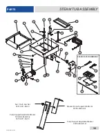
PARTS
INLET/OUTLET PLUMBING
16
5
17
6
18
19
17
7
5
5
5
Complete Outlet Plumbing Assembly
05700-003-60-75
Complete Inlet Plumbing Assembly
05700-003-60-74
Tube Length Chart
Item # Length (inches)
8
1/2” x 2 1/2” Long
9
1/2” x 37” Long
10
1/2” x 3” Long
12
1/2” x 2 1/8” Long
13
1/2” x 3 1/2” Long
17
1/2” x 30 3/4” Long
When servicing plumbing components, take care not to damage the threads of each individual item. Damaged threads can cause leaks and loss of
pressure, which could adversely affect the performance of the dishmachine. It is strongly recommended that thread tape—used in conservative amounts—
be applied to threads when joining components together. Do not use thread-sealing compounds, sometimes referred to as “pipe dope.” Compounds can
be ejected from the threads during the tightening process and become lodged in key components, rendering them useless, including solenoid valves and
pressure gauge ball valves.
NOTICE
10
10
18
17
TempStar
Summary of Contents for TEMPSTAR LT
Page 35: ...07610 003 61 42 U 28 26 1 29 28 30 33 34 36 CONTROL BOX ASSEMBLY PARTS ...
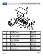
Page 67: ...07610 003 61 42 U 60 PARTS VENTLESS SYSTEM ASSEMBLY ...
Page 75: ...07610 003 61 42 U 68 SCHEMATICS 208 230 V 50 60 HZ 1 PHASE ...
Page 76: ...69 07610 003 61 42 U SCHEMATICS 460 V 50 60 HZ 3 PHASE ...
Page 77: ...07610 003 61 42 U 70 SCHEMATICS LT NB 208 230 V 50 60 HZ 1 PHASE ...
Page 78: ...71 07610 003 61 42 U SCHEMATICS LT NB 460 V 50 60 HZ 3 PHASE ...
Page 79: ...07610 003 61 42 U 72 SCHEMATICS STEAM 208 230 V 50 60 HZ 1 3 PHASE ...
Page 80: ...73 07610 003 61 42 U SCHEMATICS SDI OPTIONS ...
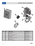
Page 81: ...07610 003 61 42 U 74 SCHEMATICS DRAIN QUENCH OPTION ...