


23
07610-003-61-42-U
7.
Place one of the washers from the kit on the rinse arm.
8.
Put the bearing from the kit on top of the washer.
9.
Place the rinse head bushing back on the rinse arm.
10.
Put the other washer from the kit on top of the rinse head bushing.
11.
Push the retaining clip from the kit into place.
12. Screw the rinse arm back on the manifold.
Work performed on dishmachines by unauthorized or unqualified personnel
may void the warranty. Before beginning this or any other maintenance on a
unit under warranty, you should contact a manufacturer-certified technician or
the manufacturer's Technical Service.
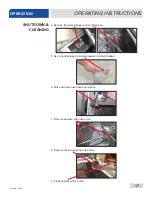
RINSE ARM MAINTENANCE
MAINTENANCE
!
CAUTION
NOTICE
BEARING
REPLACEMENT
One of the washers from
the kit is used in this step.
The bearing from the kit is
used in this step.
One of the washers from
the kit is used in this step.
The retaining clip from the
kit is used in this step.
Summary of Contents for TEMPSTAR LT
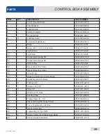
Page 35: ...07610 003 61 42 U 28 26 1 29 28 30 33 34 36 CONTROL BOX ASSEMBLY PARTS ...
Page 67: ...07610 003 61 42 U 60 PARTS VENTLESS SYSTEM ASSEMBLY ...
Page 75: ...07610 003 61 42 U 68 SCHEMATICS 208 230 V 50 60 HZ 1 PHASE ...
Page 76: ...69 07610 003 61 42 U SCHEMATICS 460 V 50 60 HZ 3 PHASE ...
Page 77: ...07610 003 61 42 U 70 SCHEMATICS LT NB 208 230 V 50 60 HZ 1 PHASE ...
Page 78: ...71 07610 003 61 42 U SCHEMATICS LT NB 460 V 50 60 HZ 3 PHASE ...
Page 79: ...07610 003 61 42 U 72 SCHEMATICS STEAM 208 230 V 50 60 HZ 1 3 PHASE ...
Page 80: ...73 07610 003 61 42 U SCHEMATICS SDI OPTIONS ...
Page 81: ...07610 003 61 42 U 74 SCHEMATICS DRAIN QUENCH OPTION ...