


Jabiru Aircraft
Pty Ptd
Aircraft Service Manual
Jabiru J230-C
REVISION
0
Dated : Feb 2006
Issued By: RAS
Page: 82 of 171
L:\files\Technical_manuals\J230_J430\J230.J430_Work_files\J230-C_Tech_Rev_1.doc
Print Date: 14/01/2009 4:41:00 PM
8
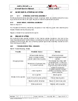
SECTION 8 - WING FLAP CONTROL SYSTEM
8.1
WING FLAP CONTROL SYSTEM
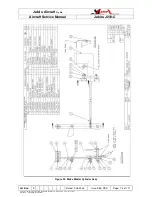
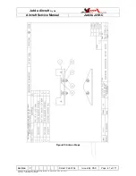
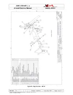
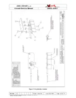
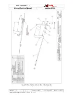
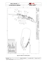
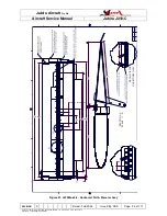
Refer to Figures 24 to 26.
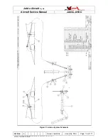
The wing flap control system comprises a switch & position indicator mounted on the
instrument panel, and a electronic linear actuator-driven common shaft assembly, with
pushrods connecting to the flap control surface horns.
WARNING
All spherical rod end bearings must be fitted with a large washer on the outside of
the through-bolt to prevent the bearing case and cable releasing in the event of a
bearing failure.
8.1.1
OPERATIONAL CHECK
Operate flaps through their full range of travel, observing for uneven or jumpy motion or
binding in the system. Ensure flaps are moving together through their full range of travel.
8.1.2
FLAP SWITCH ASSEMBLY
The flap position controlling switch uses a manual toggle switch with position indicator to
control the flap deflection.
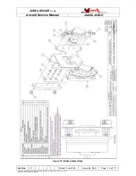
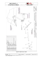
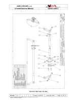
8.1.3
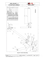
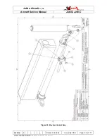
FLAP CROSS SHAFT ASSEMBLY
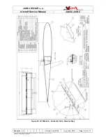
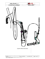
See Figure 26.
8.1.4
FLAP CROSS SHAFT REMOVAL
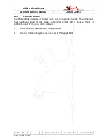
1.
Remove one wing to allow removal of shaft. Refer to Section 5.1.1 for details on
wing removal procedure.
2.
Disconnect the flap drive motor from the cross shaft input arm.
3.
Remove external flap drive arm from the end of the shaft nearest the remaining
wing.
4.
Remove the bolts holding the input arm to the flap cross shaft. If fitted, it will be
necessary to remove any upholstery and paint from the shaft to allow it to be
drawn out through the bearings on the sides of the fuselage.
5.
Draw the tube out of the fuselage.
8.1.5
FLAP CROSS SHAFT INSPECTION & REPAIR
Repair is limited to replacing worn parts. Refer to Figure 26 for guidance.
8.1.6
FLAP CROSS SHAFT INSTALLATION
Installation procedure is the reverse of assembly.