Jabiru Aircraft
Pty Ptd
Aircraft Service Manual
Jabiru J230-C
REVISION
0
Dated : Feb 2006
Issued By: RAS
Page: 114 of 171
L:\files\Technical_manuals\J230_J430\J230.J430_Work_files\J230-C_Tech_Rev_1.doc
Print Date: 14/01/2009 4:41:00 PM
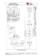
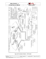
Figure 42 – Instrument Panel & Throttle Assembly
11.7.3
CHOKE
The Choke Control is located in the main instrument panel & is connected to the
carburettor by a control cable.
11.7.4
AIR INTAKE SYSTEM & CARBURETOR HEAT
The engine air intake system comprises a cold air inlet in the lower cowl, a hot air muff
attached to the exhaust system, a mixer assembly mounted on the firewall and connected
to a carburettor. The mixer box incorporates the air filter, control flaps etc.
Carburettor Heat is activated by pulling the Carburettor Heat Control on the panel OUT.
This opens the hot air valve in the mixer assembly and permits hot air to flow from the
muff into the carburettor.
The air filter should be inspected every 100 hours or more regularly if the engine is
operated in dusty conditions. Refer Paragraph 11.9. Dirty filters can be cleaned once by
blowing out with compressed air – when the filter becomes dirty again it must be replaced.
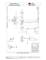
Refer to Figure 43.


