background image

Jabiru Aircraft 

Pty Ptd


Aircraft Service Manual 

Jabiru J230-C 


REVISION 


Dated : Feb 2006 

Issued By: RAS 

Page:  45 of 171 

L:\files\Technical_manuals\J230_J430\J230.J430_Work_files\J230-C_Tech_Rev_1.doc 
Print Date:  14/01/2009 4:41:00 PM 

 
13. 

Unbolt and remove front wing attachment bolt. 

 
14. 

Unbolt and remove rear wing attachment bolt. 
Note:  It may be necessary to rock the wing slightly while pulling attaching bolt, or 
carefully use a long drift punch to drive out attaching bolt. 

 
15. 

Carefully remove wing by moving it out to clear the aileron cable from the fuselage. 

 
16. 

Place wing on cushioned structure to avoid damage to wing strut attachment. 

 
17. 

Unbolt lower wing strut bolt and remove wing strut. 

 
18. 

Repeat Steps 5 – 16 to remove other wing. 

5.1.2 

REPAIR 

The  wing  is  a  composite  monocoque  structure.    All  repairs  must  be  referred  to  JABIRU 
AIRCRAFT Pty Ltd or our approved local agent. 

5.1.3 

INSTALLATION 

1. 

Fit the lower strut attaching bolt, leaving the top end of the strut on the ground. 


WARNING 

Do Not Tighten nut or metal fatigue may result.  Washer must be free to rotate. 

 
2. 

Fit  wing  to  fuselage,  leaving  wing  tip  on  the  saw-horse  and  routing  aileron  cable 
through hole in fuselage wing root. 

 
3. 

Install front and rear wing attaching bolts/nuts. 

 
4. 

Put top wing strut attaching bolt in your pocket. 

 
5. 

Lift  wing  tip  and  install  wing  strut  to  wing  strut  attachment  with  bolt  from  pocket.  
Install nut. 

WARNING 

Do Not Tighten nut or metal fatigue may result.  Washer must be free to rotate. 

 
6. 

Connect all fuel lines to wing.  Connect wires to fuel gauge sender 

WARNING 

Ensure no fuel or breather lines are kinked. 

 
7. 

Put about 10lts of fuel in each tank & check for any leaks. 

 
8. 

Attach flap to wing ensuring all bushes are in place. 

 
9. 

Install bolt/nut in flap control rod. 

 
10. 

Install bolt/nut in aileron control cable on main control stick horn. 


Summary of Contents for J230-C

Page 1: ...iles J230 C_Tech_Rev_1 doc Print Date 14 01 2009 4 41 00 PM Aircraft Service Manual Service Schedule Inspection Schedule Engine Instruction Maintenance Manual Propeller Instruction Manual Airworthines...

Page 2: ...y to become fully aware of the particular maintenance requirements and limitations applicable to the appropriate registration The details given above are intended to give owners a broad appreciation o...

Page 3: ..._files J230 C_Tech_Rev_1 doc Print Date 14 01 2009 4 41 00 PM etc maintenance is required to be done by approved persons L2 or LAME depending on the registration In the interests of product developmen...

Page 4: ...NG 18 3 1 1 Towing 18 3 1 2 Jacking 18 3 1 3 Hoisting 19 3 1 4 Levelling 20 3 1 5 Parking 20 3 1 6 Tie Down 20 3 1 7 Flyable Storage 20 3 1 8 Returning Aircraft to Service 21 3 1 9 Temporary or Indefi...

Page 5: ...RETARDANT 43 4 6 SOUNDPROOFING 43 4 7 SAFETY PROVISIONS 43 4 7 1 Seatbelts 43 5 SECTION 5 WINGS AND EMPENNAGE 44 5 1 WINGS 44 5 1 1 Removal 44 5 1 2 Repair 45 5 1 3 Installation 45 5 2 WING STRUTS 49...

Page 6: ...8 1 Trouble Shooting Brakes 68 6 8 2 Brake Master Cylinder 69 6 8 3 Hydraulic Brake Lines 69 6 8 4 Wheel Brake Assemblies 69 6 8 5 Brake System Bleeding 71 6 8 6 Brake Pad Adjustment 71 6 8 7 Parking...

Page 7: ...0 SECTION 10 RUDDER CONTROL SYSTEM 100 10 1 RUDDER PEDAL SYSTEM 100 10 1 1 Removal and Installation 100 10 1 2 Inspection and Repair 100 10 2 RUDDER 102 10 2 1 Removal Installation 102 10 2 2 Inspecti...

Page 8: ...IC Fuel GAUGE SENDER Removal Installation 128 12 6 HEADER TANK LOW LEVEL WARNING OPTION 130 12 6 1 Description 130 12 6 2 Fuel Valve Removal Installation 130 12 7 FUEL FILTERS 130 12 7 1 Fuel filter 1...

Page 9: ...1 14 10 RADIO WIRING DIAGRAM OPTION 151 14 10 1 VHF ANTENNA INSTALLATION 151 15 SECTION 15 PAINTING FINISHING 153 15 1 EXTERIOR 153 15 1 1 Painting 153 15 1 2 Materials Recommended 153 15 1 3 Painting...

Page 10: ...cal_manuals J230_J430 J230 J430_Work_files J230 C_Tech_Rev_1 doc Print Date 14 01 2009 4 41 00 PM 22 1 GENERAL 170 22 2 INTERIOR FLAME RETARDANT MAINTENANCE LIMITATIONS 170 22 3 COMPOSITE INSPECTION M...

Page 11: ...ube Assy 87 Figure 26 Flap Position Indicator 88 Figure 27 Flap Position Indicator Drive Cable Assembly 89 Figure 28 Elevator Control Assy 92 Figure 29 Elevator Control Assy Rear 93 Figure 30 J230 Mod...

Page 12: ...on Chart 33 Table 5 Trouble Shooting Main Undercarriage 52 Table 6 Trouble Shooting Nose Leg 63 Table 7 Trouble Shooting Brakes 68 Table 8 Trouble Shooting Fuel System 122 Table 9 Trouble Shooting Fue...

Page 13: ...144 1 16 5 06 25 1 16 5 06 85 1 16 5 06 145 1 16 5 06 26 1 16 5 06 86 1 16 5 06 146 1 16 5 06 27 1 16 5 06 87 1 16 5 06 147 1 16 5 06 28 1 16 5 06 88 1 16 5 06 148 1 16 5 06 29 1 16 5 06 89 1 16 5 06...

Page 14: ...aintenance ie 33 and 66 hour maintenance Refer to Engine Maintenance Manual for details Every 100 hours or Annually whichever happens first a 100 hour inspection must be inspected by an Authorised Per...

Page 15: ...tions Model J230 C Aircraft Maximum Weight 600kg 1320lb Fuel Capacity 135 litres Fuel Type AVGAS 100 130 MOGAS with Octane Rating 95 RON AKI 90 or above may be used if AVGAS is not available Fuels Con...

Page 16: ...Service Manual Jabiru J230 C REVISION 0 Dated Feb 2006 Issued By RAS Page 16 of 171 L files Technical_manuals J230_J430 J230 J430_Work_files J230 C_Tech_Rev_1 doc Print Date 14 01 2009 4 41 00 PM Fig...

Page 17: ...gine Bolt Torque Values see Engine Instruction Maintenance Manual The above values are recommended for all installation procedures contained in this Manual except where other values are stipulated The...

Page 18: ...it is Connected to the Nose Wheel The aircraft may also be moved by placing the propeller in the horizontal and then placing one hand on the propeller on either side of the spinner The aircraft can t...

Page 19: ...on top of the trestle compliant material should distribute load over minimum 150 square centimetres Place under the lower wing strut attachment 3 Support under both wings at the Wing Spar to prevent...

Page 20: ...ircraft in the open head into wind if possible Secure control surfaces by tying the control handle back firmly with a seat belt Then 1 Tie ropes to the top end of each wing strut Secure opposite end o...

Page 21: ...gasoline to prevent moisture accumulation For indefinite storage drain fuel tank ensure carburettor bowl is empty by running engine with fuel valve off until it stops or by draining bowl Then 1 Clean...

Page 22: ...the horizontal position CAUTION Ensure that the Master and Ignition Switches are OFF 3 1 10 INSPECTION DURING STORAGE 1 Generally inspect airframe and clean as necessary 2 Inspect the interior of at l...

Page 23: ...ignificant weight their weight will need to be subtracted from the relevant scale reading 3 Level the aircraft using technique in 3 1 4 Levelling If the nose needs to be raised place packers under the...

Page 24: ...g and 1mm 9 Average of the measurements taken for each quantity and the average of the two nose wheel distances are now used to calculate the aircrafts C G Figure 2 Weighing Diagram 3 3 SERVICING Serv...

Page 25: ...ld be removed inspected and cleaned will depend on the operating conditions A good general rule however is to remove inspect and clean the filter ever 100 hours of engine operating time and more frequ...

Page 26: ...d de icer fluid lacquer thinner or glass window cleaning spray These solvents will soften and craze the Plastic DO NOT use a canvas cover on the windshield or windows as the cover may scratch the plas...

Page 27: ...ntial to minimise any danger of fire and provide easy inspection of components CAUTION DO NOT hose engine Electrical components may be damaged by moisture Ensure electrical components are protected ag...

Page 28: ...erviced or otherwise completed as necessary to ensure continuous airworthiness At each 200 hours the 100 hours items would be completed in addition to the items marked under EACH 200 HOURS as necessar...

Page 29: ...m Aileron 3 25 mm 3 6 3 3 AIRFRAME STRUCTURE A visual inspection should be conducted each 100 hours Check for cracking of the paintwork whiting of unpainted areas movement of wing attachments and thre...

Page 30: ...ETAL PARTS security of attachment cracks metal distortion broken welds corrosion and any other apparent damage 3 6 3 8 WIRING security chafing burning defective insulation loose or broken terminals he...

Page 31: ...st Aircraft Registration Radio Station License Pilot License Certificate including Medical Certificate if appropriate 3 6 3 12 ENGINE RUN UP Before beginning the step by step inspection start run up a...

Page 32: ...0 C_Tech_Rev_1 doc Print Date 14 01 2009 4 41 00 PM 3 7 MAJOR INSPECTION REPLACEMENT 3 7 1 MANDATORY INSPECTION 3 7 1 1 AIRFRAME The J230 C does not have an overall airframe life limitation 3 7 1 2 UN...

Page 33: ...0 Hours Each 100 Hours PROPELLER 1 Spinner 2 Spinner Flange 3 Spinner screws 4 Propeller 5 Propeller bolts nuts Tension 6 Spinner Prop Tracking ENGINE COMPARTMENT Check for oil fuel exhaust induction...

Page 34: ...em 12 Firewall 13 Exhaust System Including Muffler 14 Fuel pressure warning light switch 15 Cabin heat system 16 Engine cowlings and clips Fuel System 1 Fuel filters drain valves carburetor bowl 2 Ele...

Page 35: ...bushes 6 Main gear struts clamps bolts nuts 7 Tyres tubes 8 Brake fluid hoses linings discs brake assemblies master cylinder 9 Rod ends condition freedom of movement 10 Brake operational check Airfram...

Page 36: ...ches 17 Stall warning 18 Battery battery cradle cables Control Systems In addition to the items listed below always check for correct direction of movement particularly if controls have been disconnec...

Page 37: ...fill in minor scratches in clear plastic and help protect the surface from further abrasion Use a good grade of commercial wax NOT SILICON BASED applied in a thin even coat Bring wax to a high polish...

Page 38: ...to remove them without destroying them Once windows have been broken out any screws used in the original installation should be removed 4 2 8 INSTALLATION 1 Ensure all old epoxy resin has been removed...

Page 39: ...aft Service Manual Jabiru J230 C REVISION 0 Dated Feb 2006 Issued By RAS Page 39 of 171 L files Technical_manuals J230_J430 J230 J430_Work_files J230 C_Tech_Rev_1 doc Print Date 14 01 2009 4 41 00 PM...

Page 40: ...raft Service Manual Jabiru J230 C REVISION 0 Dated Feb 2006 Issued By RAS Page 40 of 171 L files Technical_manuals J230_J430 J230 J430_Work_files J230 C_Tech_Rev_1 doc Print Date 14 01 2009 4 41 00 PM...

Page 41: ...art from excluding wind and water the weather strip is important in minimising exhaust fume entry to the cabin It should be maintained in good condition and fit at all times New weather strip may be a...

Page 42: ...ervice Manual Jabiru J230 C REVISION 0 Dated Feb 2006 Issued By RAS Page 42 of 171 L files Technical_manuals J230_J430 J230 J430_Work_files J230 C_Tech_Rev_1 doc Print Date 14 01 2009 4 41 00 PM Figur...

Page 43: ...sily removed for cleaning and inspection of the seat structures Note that the seat covers are treated with a flame retardant which must be re applied after every 5 washes Optional Hood and Cabin linin...

Page 44: ...hreaded bushes bonded into the attachment blocks 5 1 1 REMOVAL The JABIRU aircraft is designed with wings which are removable for storage or transport Wing removal is most easily achieved if two perso...

Page 45: ...be referred to JABIRU AIRCRAFT Pty Ltd or our approved local agent 5 1 3 INSTALLATION 1 Fit the lower strut attaching bolt leaving the top end of the strut on the ground WARNING Do Not Tighten nut or...

Page 46: ...mp in the engine compartment Have a second person catch any fuel that flows out of the line in a container with accurate volume marks Turn electric fuel pump on and pump fuel through the lines into co...

Page 47: ...Service Manual Jabiru J230 C REVISION 0 Dated Feb 2006 Issued By RAS Page 47 of 171 L files Technical_manuals J230_J430 J230 J430_Work_files J230 C_Tech_Rev_1 doc Print Date 14 01 2009 4 41 00 PM Fig...

Page 48: ...Service Manual Jabiru J230 C REVISION 0 Dated Feb 2006 Issued By RAS Page 48 of 171 L files Technical_manuals J230_J430 J230 J430_Work_files J230 C_Tech_Rev_1 doc Print Date 14 01 2009 4 41 00 PM Fig...

Page 49: ...R Wing struts are structural components and therefore all repairs must be referred to JABIRU AIRCRAFT Pty Ltd or our approved local agent A dented cracked or deformed wing strut should be replaced pri...

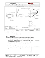
Page 50: ...GHT OPTION 5 4 1 DESCRIPTION A landing light may be fitted to the wing strut as an option refer to Figure 11 5 4 2 LANDING LIGHT REMOVAL INSTALLATION 1 Remove the screw holding the lens retainer to th...

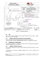
Page 51: ...1 REMOVAL INSTALLATION INSPECTION AND REPAIR The fin is an integral part of the fuselage structure and cannot be removed All repairs must be referred to JABIRU AIRCRAFT Pty Ltd or our approved local a...

Page 52: ...aft leans to one side Bent axle stubs Install new part s Incorrect tyre inflation Inflate to pressure shown in above Main wheels out of alignment Align as specified above Bent axle stubs Install new p...

Page 53: ...stall the landing gear as a complete assembly Refer to applicable paragraphs for installation of the individual components With aircraft jacked 1 Offer the beam to the fuselage and install clamp and b...

Page 54: ...MOVAL AND INSTALLATION 1 Remove the machine screws around the join of the inner and outer sections of the fairing 2 Remove the bolt on the outside of the fairing 3 Remove the machine screws 2 OFF on t...

Page 55: ...Service Manual Jabiru J230 C REVISION 0 Dated Feb 2006 Issued By RAS Page 55 of 171 L files Technical_manuals J230_J430 J230 J430_Work_files J230 C_Tech_Rev_1 doc Print Date 14 01 2009 4 41 00 PM Figu...

Page 56: ...attempting to separate wheel halves with the tyre inflated Avoid damaging wheel flanges when breaking beads loose as a scratch nick or gouge may cause wheel failure 2 Remove through bolts nuts and se...

Page 57: ...lves during assembly Uneven or improper torque of through bolt nuts can cause failure of bolts with resultant wheel failure 9 Insert through bolts through brake disc and position disc on the inner whe...

Page 58: ...s or tape them together carefully so that they can be installed in exactly the same position to ensure that wheel alignment is not disturbed 5 Remove inboard brake plate 6 4 6 MAIN WHEEL STUB AXLE INS...

Page 59: ...ft Service Manual Jabiru J230 C REVISION 0 Dated Feb 2006 Issued By RAS Page 59 of 171 L files Technical_manuals J230_J430 J230 J430_Work_files J230 C_Tech_Rev_1 doc Print Date 14 01 2009 4 41 00 PM F...

Page 60: ...t Service Manual Jabiru J230 C REVISION 0 Dated Feb 2006 Issued By RAS Page 60 of 171 L files Technical_manuals J230_J430 J230 J430_Work_files J230 C_Tech_Rev_1 doc Print Date 14 01 2009 4 41 00 PM Fi...

Page 61: ...aft Service Manual Jabiru J230 C REVISION 0 Dated Feb 2006 Issued By RAS Page 61 of 171 L files Technical_manuals J230_J430 J230 J430_Work_files J230 C_Tech_Rev_1 doc Print Date 14 01 2009 4 41 00 PM...

Page 62: ...ice Manual Jabiru J230 C REVISION 0 Dated Feb 2006 Issued By RAS Page 62 of 171 L files Technical_manuals J230_J430 J230 J430_Work_files J230 C_Tech_Rev_1 doc Print Date 14 01 2009 4 41 00 PM Figure 1...

Page 63: ...el assembly are described in separate paragraphs The wheel is in two halves which are joined by through bolts to the wheel hub as shown in Figure 18 During assembly of the nose wheel the through bolts...

Page 64: ...RING REMOVAL AND INSTALLATION 1 Remove the machine screws around the forward and rear sections of the fairing and remove the front section 2 Loosen the axle nuts and remove the rear section 3 Reverse...

Page 65: ...6 4 NOSE WHEEL REASSEMBLY 1 Replace bearings in wheel hub 2 Apply automotive wheel rim lubricant to the tyre bead faces on the inside of the wheel rims Note that if this step is skipped disassembly o...

Page 66: ...Technical_manuals J230_J430 J230 J430_Work_files J230 C_Tech_Rev_1 doc Print Date 14 01 2009 4 41 00 PM A3 VAR 6A002A0D 4 8 5 03 1 2 DS REFER TO PART DRAWINGS ISSUE 3 SHOWS NEW BEND IN LEG MODIFIED Y...

Page 67: ...t Service Manual Jabiru J230 C REVISION 0 Dated Feb 2006 Issued By RAS Page 67 of 171 L files Technical_manuals J230_J430 J230 J430_Work_files J230 C_Tech_Rev_1 doc Print Date 14 01 2009 4 41 00 PM Fi...

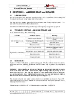
Page 68: ...linder located on the front of the main longitudinal beam flexible hoses connecting the master cylinder to each wheel brake cylinder and the single disc and a floating cylinder type brake assembly loc...

Page 69: ...system in accordance with Paragraph 6 8 5 6 8 2 2 BRAKE MASTER CYLINDER REPAIR Figure 20 may be used as a guide during disassembly repair and reassembly of the brake master cylinder Repair is limited...

Page 70: ...bolts 6 Inspect wheel brake disc for a minimum thickness of 2mm If brake disc is below minimum thickness install a new part For directional brake discs refer to Figure 16 for installation details 6 8...

Page 71: ...e inboard pad backing plate 2 Use a drill and punch to remove the rivets holding the pad onto the backing plate 3 Replace lining in accordance with steps given above 4 Install axle and wheel assembly...

Page 72: ...v_1 doc Print Date 14 01 2009 4 41 00 PM 6 8 7 PARKING BRAKE The Parking Brake consists of an over centre cam on the brake handle Should the cam have insufficient travel for the brakes to hold the air...

Page 73: ...aft Service Manual Jabiru J230 C REVISION 0 Dated Feb 2006 Issued By RAS Page 73 of 171 L files Technical_manuals J230_J430 J230 J430_Work_files J230 C_Tech_Rev_1 doc Print Date 14 01 2009 4 41 00 PM...

Page 74: ...Service Manual Jabiru J230 C REVISION 0 Dated Feb 2006 Issued By RAS Page 74 of 171 L files Technical_manuals J230_J430 J230 J430_Work_files J230 C_Tech_Rev_1 doc Print Date 14 01 2009 4 41 00 PM Figu...

Page 75: ...9 4 41 00 PM 7 SECTION 7 AILERON CONTROL SYSTEM 7 1 AILERON CONTROL SYSTEM Refer to Figure 21 The aileron control system is comprised of a control column and two enclosed push pull cables fitted with...

Page 76: ...Service Manual Jabiru J230 C REVISION 0 Dated Feb 2006 Issued By RAS Page 76 of 171 L files Technical_manuals J230_J430 J230 J430_Work_files J230 C_Tech_Rev_1 doc Print Date 14 01 2009 4 41 00 PM Fig...

Page 77: ...ck from the pivot plate 2 Unbolt and remove the aileron cable ends from the aileron drive arms at the lower end of the control column 3 Unbolt remove the aileron drive yoke from the lower end of the c...

Page 78: ...aft Service Manual Jabiru J230 C REVISION 0 Dated Feb 2006 Issued By RAS Page 78 of 171 L files Technical_manuals J230_J430 J230 J430_Work_files J230 C_Tech_Rev_1 doc Print Date 14 01 2009 4 41 00 PM...

Page 79: ...e in place to allow installation of a replacement part 7 3 2 CONTROL CABLE INSPECTION REPAIR Repair of control cables is limited to the installation of new parts 7 3 3 CONTROL CABLE INSTALLATION Insta...

Page 80: ...ce or similar measuring instrument will be required 7 5 CONTROL RIGGING 1 With the control stick in the neutral position use a straight edge not less than 1 metre long Hold the straight edge flush on...

Page 81: ...rcraft Service Manual Jabiru J230 C REVISION 0 Dated Feb 2006 Issued By RAS Page 81 of 171 L files Technical_manuals J230_J430 J230 J430_Work_files J230 C_Tech_Rev_1 doc Print Date 14 01 2009 4 41 00...

Page 82: ...ion or binding in the system Ensure flaps are moving together through their full range of travel 8 1 2 FLAP SWITCH ASSEMBLY The flap position controlling switch uses a manual toggle switch with positi...

Page 83: ...ise a moulded and bonded monocoque structure embodying a composite control arm at the inboard end 8 2 1 REMOVAL AND INSTALLATION 1 Unbolt rod end from flap control arm 2 Remove each flap hinge bolt an...

Page 84: ...C_Tech_Rev_1 doc Print Date 14 01 2009 4 41 00 PM 2 Adjust with the rod ends Ensure that the lock nut is tight on the control ends and that the thread is visible through the hole in the rod 3 Check f...

Page 85: ...ft Service Manual Jabiru J230 C REVISION 0 Dated Feb 2006 Issued By RAS Page 85 of 171 L files Technical_manuals J230_J430 J230 J430_Work_files J230 C_Tech_Rev_1 doc Print Date 14 01 2009 4 41 00 PM F...

Page 86: ...ft Service Manual Jabiru J230 C REVISION 0 Dated Feb 2006 Issued By RAS Page 86 of 171 L files Technical_manuals J230_J430 J230 J430_Work_files J230 C_Tech_Rev_1 doc Print Date 14 01 2009 4 41 00 PM F...

Page 87: ...ft Service Manual Jabiru J230 C REVISION 0 Dated Feb 2006 Issued By RAS Page 87 of 171 L files Technical_manuals J230_J430 J230 J430_Work_files J230 C_Tech_Rev_1 doc Print Date 14 01 2009 4 41 00 PM F...

Page 88: ...t Service Manual Jabiru J230 C REVISION 0 Dated Feb 2006 Issued By RAS Page 88 of 171 L files Technical_manuals J230_J430 J230 J430_Work_files J230 C_Tech_Rev_1 doc Print Date 14 01 2009 4 41 00 PM Fi...

Page 89: ...anual Jabiru J230 C REVISION 0 Dated Feb 2006 Issued By RAS Page 89 of 171 L files Technical_manuals J230_J430 J230 J430_Work_files J230 C_Tech_Rev_1 doc Print Date 14 01 2009 4 41 00 PM Figure 28 Fla...

Page 90: ...he elevator comprises a Rigid Cellular Polystyrene core moulded and bonded to a composite skin and embodying a composite control horn at the centre An elevator trim system is attached Refer Paragraph...

Page 91: ...AND INSTALLATION The Control Cable is a Primary Control and may not be repaired or removed without reference to JABIRU AIRCRAFT Pty Ltd or our approved local agent 9 5 RIGGING 1 Refer to Figure 33 2...

Page 92: ...ft Service Manual Jabiru J230 C REVISION 0 Dated Feb 2006 Issued By RAS Page 92 of 171 L files Technical_manuals J230_J430 J230 J430_Work_files J230 C_Tech_Rev_1 doc Print Date 14 01 2009 4 41 00 PM F...

Page 93: ...Service Manual Jabiru J230 C REVISION 0 Dated Feb 2006 Issued By RAS Page 93 of 171 L files Technical_manuals J230_J430 J230 J430_Work_files J230 C_Tech_Rev_1 doc Print Date 14 01 2009 4 41 00 PM Figu...

Page 94: ...Technical_manuals J230_J430 J230 J430_Work_files J230 C_Tech_Rev_1 doc Print Date 14 01 2009 4 41 00 PM 8 4 02 314 299 2205 2350 2210 DETAIL VIEW E UL D MODEL ONLY 400 155 280 GAP BETWEEN VG 1900 296...

Page 95: ...Manual Jabiru J230 C REVISION 0 Dated Feb 2006 Issued By RAS Page 95 of 171 L files Technical_manuals J230_J430 J230 J430_Work_files J230 C_Tech_Rev_1 doc Print Date 14 01 2009 4 41 00 PM Figure 32 J...

Page 96: ...t Service Manual Jabiru J230 C REVISION 0 Dated Feb 2006 Issued By RAS Page 96 of 171 L files Technical_manuals J230_J430 J230 J430_Work_files J230 C_Tech_Rev_1 doc Print Date 14 01 2009 4 41 00 PM Fi...

Page 97: ...and AFT and movement of the Elevator UP and DOWN See Figure 34 WARNING It is important to carry out this operational check whenever the trim cable has been disconnected to ensure it has been correctly...

Page 98: ...Service Manual Jabiru J230 C REVISION 0 Dated Feb 2006 Issued By RAS Page 98 of 171 L files Technical_manuals J230_J430 J230 J430_Work_files J230 C_Tech_Rev_1 doc Print Date 14 01 2009 4 41 00 PM Fig...

Page 99: ...20365 428 1 4 NYLOC NUT 1 21 PB0078N BEARING DEEP GROOVE EE2 2RS 2 22 3103284 BEARING RETAINER TRIM CONTROL 1 23 3103184 BEARING PIVOT MOUNT BLOCK 1 24 PH0199N 1 8 AL POP RIVET CPNo 73AS4 6 6 25 30432...

Page 100: ...sed of rudder pedals two push rods a centering mechanism and an enclosed push pull cable 10 1 1 REMOVAL AND INSTALLATION 1 Unbolt push pull cable 2 Unbolt both steering push rods 3 Unbolt rudder pedal...

Page 101: ...aft Service Manual Jabiru J230 C REVISION 0 Dated Feb 2006 Issued By RAS Page 101 of 171 L files Technical_manuals J230_J430 J230 J430_Work_files J230 C_Tech_Rev_1 doc Print Date 14 01 2009 4 41 00 PM...

Page 102: ...cable must be clamped firmly at each end 10 3 1 REMOVAL INSTALLATION The Control Cable is a Primary Control and may not be repaired or removed without reference to JABIRU AIRCRAFT Pty Ltd or our appr...

Page 103: ...n referenced to the lower lip of the fin 4 Adjust the rod ends on the cable so that the hole in the rear rod end aligns with the hole in the control horn 5 Fit bolt nut and washers 6 Scribe a line fro...

Page 104: ...Service Manual Jabiru J230 C REVISION 0 Dated Feb 2006 Issued By RAS Page 104 of 171 L files Technical_manuals J230_J430 J230 J430_Work_files J230 C_Tech_Rev_1 doc Print Date 14 01 2009 4 41 00 PM Fi...

Page 105: ...ft Service Manual Jabiru J230 C REVISION 0 Dated Feb 2006 Issued By RAS Page 105 of 171 L files Technical_manuals J230_J430 J230 J430_Work_files J230 C_Tech_Rev_1 doc Print Date 14 01 2009 4 41 00 PM...

Page 106: ...anchor nuts 11 1 1 ENGINE COWLS REMOVAL INSTALLATION 11 1 1 1 UPPER COWL Refer to Figure 39 1 Remove the Cam Locks from the front rear of the cowling 2 Remove Hinge Pin 3 Grasping the cowl around the...

Page 107: ...raft Service Manual Jabiru J230 C REVISION 0 Dated Feb 2006 Issued By RAS Page 107 of 171 L files Technical_manuals J230_J430 J230 J430_Work_files J230 C_Tech_Rev_1 doc Print Date 14 01 2009 4 41 00 P...

Page 108: ...raft Service Manual Jabiru J230 C REVISION 0 Dated Feb 2006 Issued By RAS Page 108 of 171 L files Technical_manuals J230_J430 J230 J430_Work_files J230 C_Tech_Rev_1 doc Print Date 14 01 2009 4 41 00 P...

Page 109: ...xed pitch wooden propeller The front Starboard cylinder is numbered 1 the front Port is numbered 2 the centre Starboard is numbered 3 the centre Port is numbered 4 the rear Starboard is numbered 5 and...

Page 110: ...s for stiffness 4 All flexible hoses in the engine compartment should be replaced at engine overhaul or every 2 years whichever comes first Hoses which show visible deterioration cracking excessive ha...

Page 111: ...t of rubber seals Rubber seals may be replaced by removing the existing rubber parts rubbing back the bonding face of the fiberglass baffles to bare glass using 80 grit sandpaper or similar and bondin...

Page 112: ...p and the carbuettor 4 All fuel lines inside the cabin are housed within plastic sheath This sheathing must be maintained in good condition 5 The main fuel valve is located on the Main Beam in the cab...

Page 113: ...ice Manual Jabiru J230 C REVISION 0 Dated Feb 2006 Issued By RAS Page 113 of 171 L files Technical_manuals J230_J430 J230 J430_Work_files J230 C_Tech_Rev_1 doc Print Date 14 01 2009 4 41 00 PM Figure...

Page 114: ...ir inlet in the lower cowl a hot air muff attached to the exhaust system a mixer assembly mounted on the firewall and connected to a carburettor The mixer box incorporates the air filter control flaps...

Page 115: ...ft Service Manual Jabiru J230 C REVISION 0 Dated Feb 2006 Issued By RAS Page 115 of 171 L files Technical_manuals J230_J430 J230 J430_Work_files J230 C_Tech_Rev_1 doc Print Date 14 01 2009 4 41 00 PM...

Page 116: ...st systems are subject to burning cracking and general deterioration from alternate thermal stress and vibration inspection is very important and should be carried out every 100 hours of operation In...

Page 117: ...craft Service Manual Jabiru J230 C REVISION 0 Dated Feb 2006 Issued By RAS Page 117 of 171 L files Technical_manuals J230_J430 J230 J430_Work_files J230 C_Tech_Rev_1 doc Print Date 14 01 2009 4 41 00...

Page 118: ...ystem is probably the greatest single cause of early engine wear When operating under high dust conditions the carburettor air filters should be serviced regularly as outlined in Paragraph 11 7 4 Serv...

Page 119: ...ft Service Manual Jabiru J230 C REVISION 0 Dated Feb 2006 Issued By RAS Page 119 of 171 L files Technical_manuals J230_J430 J230 J430_Work_files J230 C_Tech_Rev_1 doc Print Date 14 01 2009 4 41 00 PM...

Page 120: ...46 2 The 5 Litre header tank is housed in an enclosure behind the rear cockpit bulkhead This enclosure is sealed from the cabin vented overboard 3 The fuel filter and auxiliary electronic fuel pump ar...

Page 121: ...ice Manual Jabiru J230 C REVISION 0 Dated Feb 2006 Issued By RAS Page 121 of 171 L files Technical_manuals J230_J430 J230 J430_Work_files J230 C_Tech_Rev_1 doc Print Date 14 01 2009 4 41 00 PM Figure...

Page 122: ...flow from preceding causes Use the preceding remedies Plugged fuel vent See Paragraph 11 3 Fuel Starvation after starting Water in fuel Drain fuel tank sump fuel lines and filter 12 2 FUEL TANK 12 2...

Page 123: ...expanding fuel pressurising the tank The following procedure may be used to check the tank and tube 1 Have an assistant hold a rubber glove or balloon over the vent tube on one cap 2 Blow into the ca...

Page 124: ...30_Work_files J230 C_Tech_Rev_1 doc Print Date 14 01 2009 4 41 00 PM 2 An alternative method which may be used is to fill the wing tanks with fuel then shake the aircraft by pushing up and down on the...

Page 125: ...ft Service Manual Jabiru J230 C REVISION 0 Dated Feb 2006 Issued By RAS Page 125 of 171 L files Technical_manuals J230_J430 J230 J430_Work_files J230 C_Tech_Rev_1 doc Print Date 14 01 2009 4 41 00 PM...

Page 126: ...located in front of the main longitudinal beam 12 4 2 FUEL VALVE REMOVAL INSTALLATION 1 Turn OFF both taps between wing tanks and header tank Cover both tank cap vents On LSA models the fuel system mu...

Page 127: ...nd uses senders in the tanks to drive electronic LCD gauges fitted in the instrument panel NOTE Both gauges are intended to require no servicing the information below is provided for reference 12 5 1...

Page 128: ...robable Cause Remedy Bad connection between sender gauge Fix connection Gauge on panel reads full tanks low Sender has lost calibration Remove sender re calibrate 12 5 4 ELECTRIC FUEL GAUGE SENDER REM...

Page 129: ...J230 C REVISION 0 Dated Feb 2006 Issued By RAS Page 129 of 171 L files Technical_manuals J230_J430 J230 J430_Work_files J230 C_Tech_Rev_1 doc Print Date 14 01 2009 4 41 00 PM Figure 50 Fuel Gauge Ele...

Page 130: ...state LED which illuminates a red warning light on the instrument panel if the fuel level in the header tank falls below approximately 3 litres 12 6 2 FUEL VALVE REMOVAL INSTALLATION 4 Remove the hea...

Page 131: ...ng steps for installation Ensure waste cloth is removed WARNING Ensure wing tank cap vent covers are removed The fuel filter must only be installed in one direction An arrow on the side of the filter...

Page 132: ...relatively inexpensive and repairs will usually cost more than a new instrument Flight instruments on the other hand are usually well worth repairing The words replace instrument in the text therefor...

Page 133: ...REVISION 0 Dated Feb 2006 Issued By RAS Page 133 of 171 L files Technical_manuals J230_J430 J230 J430_Work_files J230 C_Tech_Rev_1 doc Print Date 14 01 2009 4 41 00 PM 13 2 2 INSTRUMENTS Refer to Fig...

Page 134: ...d damage and entrance of foreign matter Wire terminals should be insulated or tied up so that accidental ground or short circuiting will not occur 13 2 4 INSTALLATION Generally the installation proced...

Page 135: ...rain or moisture the water traps should be checked and if necessary drained 13 3 2 STATIC PRESSURE SYSTEM INSPECTION LEAKAGE TEST The following procedure outlines inspection and testing of the static...

Page 136: ...replace parts found to be defective 7 Reconnect airspeed and vertical speed indicators into static pressure systems and repeat leakage test steps 3 through 6 13 3 3 PITOT SYSTEM INSPECTION LEAKAGE TE...

Page 137: ...nd static tubing is removed in the usual manner Installation of tubing will be simplified if a guide wire is drawn in as the tubing is removed When replacing tubing and fittings tighten connections fi...

Page 138: ...Defective mechanism or leaking diaphragm Substitute known good indicator and check reading Replace instrument Excessive vibration Check panel shock mounts Replace defective shock mounts Hand vibrates...

Page 139: ...hten connections Partially plugged static line Check line for obstructions Blow out lines Ruptured diaphragm Substitute known good indicator and check reading Replace instrument Incorrect indication P...

Page 140: ...Manual Jabiru J230 C REVISION 0 Dated Feb 2006 Issued By RAS Page 140 of 171 L files Technical_manuals J230_J430 J230 J430_Work_files J230 C_Tech_Rev_1 doc Print Date 14 01 2009 4 41 00 PM Figure 55 P...

Page 141: ...Service Manual Jabiru J230 C REVISION 0 Dated Feb 2006 Issued By RAS Page 141 of 171 L files Technical_manuals J230_J430 J230 J430_Work_files J230 C_Tech_Rev_1 doc Print Date 14 01 2009 4 41 00 PM Fi...

Page 142: ...ervice Manual Jabiru J230 C REVISION 0 Dated Feb 2006 Issued By RAS Page 142 of 171 L files Technical_manuals J230_J430 J230 J430_Work_files J230 C_Tech_Rev_1 doc Print Date 14 01 2009 4 41 00 PM Figu...

Page 143: ...430 J230 J430_Work_files J230 C_Tech_Rev_1 doc Print Date 14 01 2009 4 41 00 PM Figure 58 Static System Test 13 4 TACHOMETER The tachometer is electronic and driven from a magnetic pick up Should the...

Page 144: ...on Maintenance Manual 4 Refer to an Authorised Service Centre to have Alternator and Regulator checked 5 Refer instrument to VDO Service Centre or JABIRU AIRCRAFT Pty Ltd for inspection and possible r...

Page 145: ...ouple instrument and is not connected to the aircraft electrical system See Wiring Diagram Figure 59 Should the instrument fail to operate 1 Check for loose terminal connections and damage to wiring 2...

Page 146: ...ed Vertical Speed Heading G acceleration System voltage Angle of attack Outside air temperature Roll angle Pitch artificial horizon Balance ball Clock The EFIS incorporates an internal battery to allo...

Page 147: ...current single wire negative ground electrical system A 12 volt battery supplies power for starting and furnishes a reserve source of power in the event of electrical power system failure An engine dr...

Page 148: ...t Service Manual Jabiru J230 C REVISION 0 Dated Feb 2006 Issued By RAS Page 148 of 171 L files Technical_manuals J230_J430 J230 J430_Work_files J230 C_Tech_Rev_1 doc Print Date 14 01 2009 4 41 00 PM F...

Page 149: ...t Service Manual Jabiru J230 C REVISION 0 Dated Feb 2006 Issued By RAS Page 149 of 171 L files Technical_manuals J230_J430 J230 J430_Work_files J230 C_Tech_Rev_1 doc Print Date 14 01 2009 4 41 00 PM F...

Page 150: ...14 4 2 BATTERY TROUBLE SHOOTING Trouble Shooting is limited to inspection of wiring and terminals battery charge condition and battery solenoid 14 4 3 REMOVAL AND INSTALLATION 1 Disconnect the battery...

Page 151: ...installed in the rear lower fuselage or in the cabin roof The power source for the strobe light is located behind the fuel tank WARNING The strobe system is a high voltage device Do Not remove or touc...

Page 152: ...Service Manual Jabiru J230 C REVISION 0 Dated Feb 2006 Issued By RAS Page 152 of 171 L files Technical_manuals J230_J430 J230 J430_Work_files J230 C_Tech_Rev_1 doc Print Date 14 01 2009 4 41 00 PM Fi...

Page 153: ...short course may be available from TAFE NOTE It is very easy to dramatically increase the weight of the aircraft with a heavy paint job Care must be taken to use the absolute minimum amounts of fille...

Page 154: ...7 On large radius e g sides of fuselage an extra large homemade spatula 9 thin tin plate is very handy when applying Body Filler 8 When filling up to window edges grind chamfer onto edge of window to...

Page 155: ...r not hide lumps bumps scratches and holes blow off the dust and give an all over wipe with a tack cloth to pick up the final dust particles 15 Wash down the floor of the spray area to settle dust and...

Page 156: ...0D Fitted above windscreen in front of wing carry through beam across to the left side Compass Card P No 5123024 Fit in compass card holder attached to compass EFIS Warning P No 5A042A0D 1 OFF Fit to...

Page 157: ...ng Limitations P No 5A056A0D Fitted on inside of fuselage of RHS of cabin below Rear Window Engine Oil Details P No 5A008A0D 1 OFF Attach to upper cowl beside oil door or to oil door itself Nose Wheel...

Page 158: ...HT OWNERS MANUAL Fitted to Inside of RH Door above the Door Pocket Door Open LHS P No5027094 OPEN Fitted to the Outsides of LH Door Above the Door Catch Lever Door Open RHS P No 5028094 OPEN Fitted to...

Page 159: ...9N Fitted on the Main Beam in front of the Fuel SELECTOR Valve Choke Cable P No5051094 CHOKE PULL ON Fitted at the base of the choke cable Carby Heat P No 5026194 CARB HEAT PULL ON Fitted at the base...

Page 160: ...hed using self tapping screws The fairing can be removed once these screws have been taken out When removing the wing strut fairings care should be take to avoid scratching the strut Installation is t...

Page 161: ...k_files J230 C_Tech_Rev_1 doc Print Date 14 01 2009 4 41 00 PM 18 APPENDIX I JABIRU 3300 ENGINE Appendix 1 of this Manual is the Instruction and Maintenance Manual for the Jabiru 3300 engine Please in...

Page 162: ...2 of 171 L files Technical_manuals J230_J430 J230 J430_Work_files J230 C_Tech_Rev_1 doc Print Date 14 01 2009 4 41 00 PM 19 APPENDIX II JABIRU ENGINE PARTS BOOK Please insert your copy of the INSTRUCT...

Page 163: ...age 163 of 171 L files Technical_manuals J230_J430 J230 J430_Work_files J230 C_Tech_Rev_1 doc Print Date 14 01 2009 4 41 00 PM 20 APPENDIX III ENGINE INSTALLATION MANUAL Please insert your copy of the...

Page 164: ...ith the particulars indicated below 1 The Propeller Drawing No 2 The diameter and pitches in metres proceeded by the letters D and P respectively 3 The type of engine for which the propeller has been...

Page 165: ...E WITH PROPELLER DISCONNECTED OR ENGINE DAMAGE WILL RESULT 21 4 INSTALLATION Refer to Figure 62 The Propeller is bolted to the Propeller Drive Flange with 6 x AN4 aircraft grade bolts attaching to Nyl...

Page 166: ...t Service Manual Jabiru J230 C REVISION 0 Dated May 2006 Issued By RAS Page 166 of 171 L files Technical_manuals J230_J430 J230 J430_Work_files J230 C_Tech_Rev_1 doc Print Date 14 01 2009 4 41 00 PM F...

Page 167: ...s can cause propeller fretting and engine damage 3 Fit Propeller Bolts 6 off 4 Fit front spinner backing plate to front of propeller The fit Aluminium Propeller Flange Belleville Washers 48 off 8 per...

Page 168: ...ibed above may be repaired All propellers with cracks or splits or any delamination of the composite sheath in the case of sheathed Propellers must be either Rejected as unserviceable or returned to J...

Page 169: ...ting a 16mm tube to firmly fit the centre mounting hole of the Propeller and balancing on knife edges Tolerances Imbalance shall not exceed the following limit whatever the position of the Propeller i...

Page 170: ...iru approval to inspect maintain J230 C structures Note that this does not include repairs Repairs of structural parts must be referred to Jabiru Aircraft 22 3 1 EXTERNAL PAINT FINISHING LIMITATIONS T...

Page 171: ...1150g 100g 7 4 3 AILERON BALANCING Elevator 323300g mm 4000g mm 5000g 100g 9 3 2 ELEVATOR BALANCING 22 4 1 1 CABLES Cables must be inspected as detailed in 3 6 3 2 CONTROL CABLE INSPECTIONS Table 20...

Reviews: