


Jabiru Aircraft
Pty Ptd
Aircraft Service Manual
Jabiru J230-C
REVISION
0
Dated : Feb 2006
Issued By: RAS
Page: 132 of 171
L:\files\Technical_manuals\J230_J430\J230.J430_Work_files\J230-C_Tech_Rev_1.doc
Print Date: 14/01/2009 4:41:00 PM
13
SECTION 13 – INSTRUMENTS & INSTRUMENT
SYSTEMS
13.1 GENERAL
This Section describes the typical instrument installation and its operating system.
Emphasis is placed on trouble shooting and corrective measures only. It does NOT deal
with specific instrument repairs as this usually requires special equipment and data and
should be handled by instrument specialists. Malfunctioning instruments should be either
returned to JABIRU AIRCRAFT Pty Ltd or sent to an approved instrument overhaul and
repair station for servicing.
Our concern here is with preventive maintenance on the various instrument systems and
correction of system faults which will result in instrument malfunctions. The descriptive
material, maintenance and trouble shooting information in this Section is intended to help
the owner or mechanic determine malfunctions and correct them, up to the defective
instrument itself, at which point an instrument technician should be called in. Some
instruments, such as Oil Temperature and Pressure Gauges, are simple and relatively
inexpensive and repairs will usually cost more than a new instrument. Flight instruments,
on the other hand, are usually well worth repairing. The words “replace instrument” in the
text, therefore, should be taken only in the sense of physical replacement in the aircraft.
Whether replacement is to be with a new instrument, an exchange one, or an original
instrument is to be repaired must be decided on the basis of the individual circumstances.
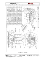
13.2 INSTRUMENT PANEL
The instrument panel assembly consists of a stationary panel. The instruments are
screw-mounted to the panel. Two different-sized instrument panels are offered with the
J230-C – both using the same construction and assembly procedures.
13.2.1
INSTRUMENT PANEL REMOVAL & INSTALLATION
The panel is secured to the Firewall and for normal maintenance is not considered
removable. Access to instruments etc is gained by removing the panel fascia containing
the instruments from the fascia.
1.
Unscrew & remove the fascia retaining screws from around the perimeter if the
panel.
2.
If the panel is to be completely removed unscrew throttle knobs. Otherwise the
panel maybe be supported up 75mm (3”) from the panel on the throttle shafts.
3.
Remove the front fascia. It is normally best to lie the fascia on a cushion or similar
while working to reduce the risk of damaging the instruments or fascia.
4.
Take care not to strain connections on wires or tubes.
5.
Assembly is the reverse of the above procedure.


