


Jabiru Aircraft
Pty Ptd
Aircraft Service Manual
Jabiru J230-C
REVISION
0
Dated : Feb 2006
Issued By: RAS
Page: 57 of 171
L:\files\Technical_manuals\J230_J430\J230.J430_Work_files\J230-C_Tech_Rev_1.doc
Print Date: 14/01/2009 4:41:00 PM
Bearings are pre-packed.
DO NOT
clean with solvents as it will remove the
packing.
5.
Replace bearings.
6.
Apply automotive wheel rim lubricant to the bead areas of the rim halves. Note that
If this step is missed, disassembly of the wheels in future will be very much harder.
7.
Position tyre and tube between wheel halves with tube inflation valve through hole
in outside wheel half.
8.
Mate wheel halves. While holding halves together, assemble a washer and nut on
one through-bolt and tighten snugly. Assemble the remaining washers and nuts on
the through-bolts and torque to the value specified in Table 2.
CAUTION
Ensure tube is not pinched between wheel halves during assembly. Uneven or
improper torque of through-bolt nuts can cause failure of bolts with resultant wheel
failure.
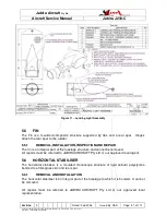
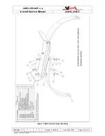
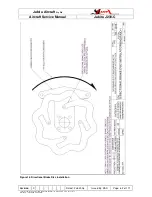
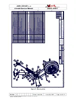
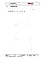
9.
Insert through-bolts through brake disc and position disc on the inner wheel hub
flange. Note that if directional brake discs are fitted, the discs must be oriented in
for the correct direction of rotation. Refer to Figure 16 below.
10.
Inflate tyre to seat tyre beads, then adjust to correct tyre pressure – Refer Aircraft
Specifications above.
6.4.4
MAIN WHEEL INSTALLATION
1.
Lightly coat axle with “Anti Sieze” or a Water Proof grease.
2.
Place wheel assembly on axle.
3.
Install spacer and lock bolt/nut through centre of axle.
4.
Place outboard brake pad plate and springs in position and secure with
bolts/nuts/washers.
5.
Reconnect flexible brake line.
6.
Refill brake master cylinder with fresh brake fluid.
7.
Bleed brakes – Refer to Section 6.8.5.
8.
Install speed fairing (if used) as outlined in Paragraph 6.3.4.
6.4.5
MAIN WHEEL STUB AXLE REMOVAL
1.
Remove speed fairing (if installed) in accordance with Paragraph 6.3.4.
2.
Remove wheel in accordance with Paragraph 6.4.1.