


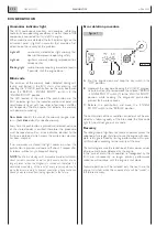


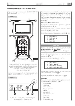


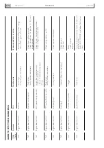
Engine diagnosing must be done with the IVECO MOTORS
PT-01 instrument.
1. USB Indicator light - 2. LEDs signalling communication
between instrument and central unit, and correct power
supply - 3. Connector to engine diagnosing outlet -
4. Connector for outside power supply -
5. Serial port indicator light.
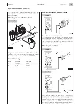
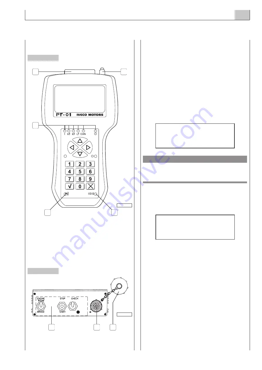
Connect the instrument with the dedicated cable to the
diagnosis connector J1(2) on the relay box (Fig. 3).
1. Relay box - 2. Connector for external diagnosis
instrument (J1) - 3. Protective cap.
The instrument is powered directly from the diagnosing out-
let. In case of prolonged use with the engine off, the instru-
ment can be powered externally through the connector (4)
of Fig.2.
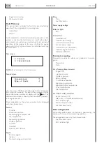
After establishing the connection between the instrument
and the diagnosing outlet, the instrument displays available
applications.
Functions of the Instrument
Through the numeric keypad (0 ÷ 9) select the application
and confirm it with the
key.
The second screen shows information about the software
version of the selected application.
To start the actual diagnosis procedure, press the
key.
CAUTION
The two arrows
, when present, signal that other
options are available but not displayed.
To display them, use the
▲
▲
▲
▲
▼
▼
▼
▼
arrows on the keypad.
To access the diagnosing procedure, press the
1
key and con-
firm with the
key.
The instrument displays the following options:
The operation is selected by pressing the associated numer-
ic key and confirming it with the
key.
To go back to the previous screen, press the
⌧
key.
Identifier
This option allows to obtain the following information, relat-
ing specifically to the central unit system:
-
Operator code
-
Station type
-
Station number
-
Date programmed
-
Release
-
Type of ECU
-
ECU software version
-
Job Number
-
Engine type
-
Original engine type
N60 ENT M37
DIAGNOSTICS
4.97
APRIL 2004
Figure 2
Figure 3
1
5
4
3
2
04_083_N
2
1
04_074_N
3
DIAGNOSING WITH PT-01 INSTRUMENT
1. Diagnosing
2. Programming
3. Utility
4. Download
1. Identifier
2. Fault memory
3. Parameter reading
4. Active diagnostics
Summary of Contents for N60 ENT M37
Page 4: ...N60 ENT M37 IV APRIL 2004 ...
Page 52: ...N60 ENT M37 OVERVIEW 1 52 APRIL 2004 ...
Page 54: ...N60 ENT M37 TECHNICAL DATA 2 54 APRIL 2004 ...
Page 60: ...N60 ENT M37 TECHNICAL DATA 2 60 APRIL 2004 ...
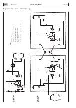
Page 62: ...N60 ENT M37 ELECTRICAL EQUIPMENT 3 62 APRIL 2004 ...
Page 92: ...N60 ENT M37 DIAGNOSTICS 4 92 APRIL 2004 ...
Page 116: ...N60 ENT M37 DIAGNOSTICS 4 116 APRIL 2004 ...
Page 118: ...N60 ENT M37 MAINTENANCE 5 118 APRIL 2004 ...
Page 122: ...N60 ENT M37 MAINTENANCE 5 122 APRIL 2004 ...
Page 124: ...N60 ENT M37 SERVICING OPERATIONS ON INSTALLED ENGINE 6 124 APRIL 2004 ...
Page 139: ...SECTION 7 TOOLS Page TOOLS 141 N60 ENT M37 TOOLS 7 139 APRIL 2004 ...
Page 140: ...N60 ENT M37 TOOLS 7 140 APRIL 2004 ...
Page 146: ...N60 ENT M37 TOOLS 7 146 APRIL 2004 ...
Page 156: ...APRIL 2004 OVERHAUL 8 156 N60 ENT M37 ...
Page 164: ...APRIL 2004 OVERHAUL 8 164 N60 ENT M37 ...
Page 181: ...OVERHAUL APRIL 2004 N60 ENT M37 8 181 ...
Page 188: ...N60 ENT M37 OVERHAUL 8 188 APRIL 2004 ...
Page 190: ...N60 ENT M37 SAFETY PRESCRIPTIONS 9 190 APRIL 2004 ...
Page 193: ......