


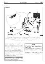


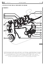


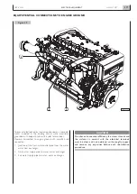


1. Engine control selector on bridge or engine room (SW1)
- 2. Manual throttle control in engine room (SW2) -
3. Pushbutton for blink code query (SW3) -
4. LED signalling anomalies EDC and blink code (DL1) -
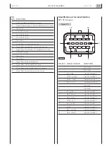
5. Connector for external diagnosis instrument (J1)
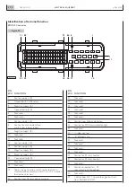
It is the main point of interconnection and carries out many
interfacing functions among the various components of the
system. The electrical commands positioned on the panel
allow to control engine starting and stopping (2) directly
from the engine room, while excluding any possibility that
anyone may involuntarily start the engine from the bridge
(1), during servicing operations.
Among the controls present on the panel are also the push-
button (3) and the “blink code” light indicator (4), useful to
obtain, also while underway, indications that will lead to iden-
tify failures or improper engine operating conditions (see
Section 4). Inside the box, anchored to a printed circuit
board, are present the power management relays of some
components and the elements that protect the electrical
lines against shor t circuits or excessive current
absorption.These components perform a similar function to
that of fuses, almost totally avoiding the need to restore the
electrical continuity of circuits subjected to an anomaly con-
dition.These components are able to limit and eliminate
short circuit currents without melting, restoring their own
and the circuit’s electrical continuity, once the cause of the
anomaly is removed.
On the relay box is located the multipolar connector,
protected by a screw-on lid (5), for connection with the
computerized diagnostic tools prescribed by IVECO
MOTORS (see Section 4).
This shall be installed and anchored in such a way as to
dampen the vibrations and stresses occurring when under-
way, and they shall be accessible during servicing operations
and when underway.
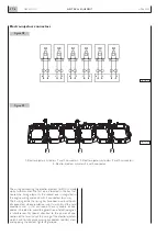
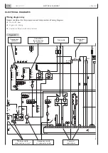
Relays contained in the relay box
K1. Fuel filter heater element power supply
K2. Power supply to terminal 50 of the electric starter
motor
K3. Key switch electric discharge
K4. Emergency engine shut-down provision
K5. Start request signal, from key switch to EDC electronic
unit
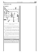
RPM control
To allow easily to control engine RPM from the “engine
room”, a simultaneous acceleration/deceleration function
(SET+/SET–), active only when the switch (1) is in the
“ENGINE ROOM” position, has been implemented in the
“start” function.
Acceleration (SET +)
If, when the engine is running, the “start - stop” push-button
is held down in the “start” position, then engine rpm are pro-
gressively increased; the increase ends when the push-butto-
nis released, allowing the engine to run at the desired rpm.
Deceleration (SET –)
Moving the “start - stop” push-button back to the “start”
position, after releasing it during the rpm increase phase, a
progressive reduction in rpm is obtained; when the push-but-
ton is release, the function is inhibited and the rpm reached
at that point is maintained.
NOTE
: Further action on the push-button will alternatively
increase - decrease engine rpm.
The “stop” function takes priority and always stops the engine.
CAUTION
Never operate the “BRIDGE - ENGINE ROOM” switch
when the engine is running.
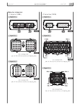
Diagnosis connector J1
N60 ENT M37
ELECTRICAL EQUIPMENT
3.70
APRIL 2004
5
3
2
1
4
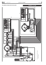
Figure 10
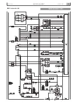
Figure 11
H
G
F
J
K
L
D
P
S
T
U
V
E
R
A
M
N
B
C
04_084_N
04_074_N
RELAY BOX
Summary of Contents for N60 ENT M37
Page 4: ...N60 ENT M37 IV APRIL 2004 ...
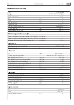
Page 52: ...N60 ENT M37 OVERVIEW 1 52 APRIL 2004 ...
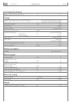
Page 54: ...N60 ENT M37 TECHNICAL DATA 2 54 APRIL 2004 ...
Page 60: ...N60 ENT M37 TECHNICAL DATA 2 60 APRIL 2004 ...
Page 62: ...N60 ENT M37 ELECTRICAL EQUIPMENT 3 62 APRIL 2004 ...
Page 92: ...N60 ENT M37 DIAGNOSTICS 4 92 APRIL 2004 ...
Page 116: ...N60 ENT M37 DIAGNOSTICS 4 116 APRIL 2004 ...
Page 118: ...N60 ENT M37 MAINTENANCE 5 118 APRIL 2004 ...
Page 122: ...N60 ENT M37 MAINTENANCE 5 122 APRIL 2004 ...
Page 124: ...N60 ENT M37 SERVICING OPERATIONS ON INSTALLED ENGINE 6 124 APRIL 2004 ...
Page 139: ...SECTION 7 TOOLS Page TOOLS 141 N60 ENT M37 TOOLS 7 139 APRIL 2004 ...
Page 140: ...N60 ENT M37 TOOLS 7 140 APRIL 2004 ...
Page 146: ...N60 ENT M37 TOOLS 7 146 APRIL 2004 ...
Page 156: ...APRIL 2004 OVERHAUL 8 156 N60 ENT M37 ...
Page 164: ...APRIL 2004 OVERHAUL 8 164 N60 ENT M37 ...
Page 181: ...OVERHAUL APRIL 2004 N60 ENT M37 8 181 ...
Page 188: ...N60 ENT M37 OVERHAUL 8 188 APRIL 2004 ...
Page 190: ...N60 ENT M37 SAFETY PRESCRIPTIONS 9 190 APRIL 2004 ...
Page 193: ......