i-ALERT2 Application Guide
20 of 64
INSTALLATION BEST PRACTICES
MOUNTING LOCATIONS
GENERAL GUIDELINES
In general the ideal place to mount the i-ALERT2 device is as close as possible to the machines bearings in a place where the
LEDs can be easily observed. Since the primary function of the i-ALERT2 device is to monitor for changes in condition, it is
not critical that the device be placed in the “load zone” of the bearing. Doing so may give a more accurate amplitude
reading, but may obscure the LEDs which are used for local status indication.
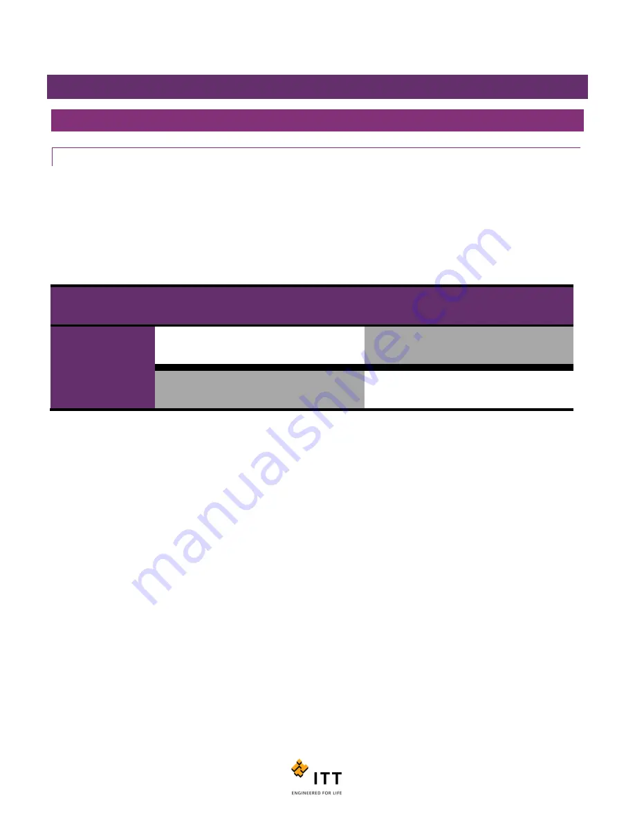
In general, a standard machine train consisting of a driver and driven piece of equipment can be monitored by 2 i-ALERT2
devices. Up to 4 monitors can be installed per machine train, one at each bearing if necessary.
Machine Type
Non-Drive End
Bearing
Drive End Bearing
Drive End Bearing
Non-Drive End
Bearing
Driver
Optional
Recommended
Driven Machine
Recommended
Optional
Figure 11: Recommended monitoring points
Summary of Contents for i-ALERT2
Page 1: ...Application Guide...
Page 2: ...i ALERT2 Application Guide 2 of 64...
Page 32: ...i ALERT2 Application Guide 32 of 64 Figure 27 Devices in range and out of range...
Page 58: ...i ALERT2 Application Guide 58 of 64 Figure 57 Route Report Trend Details Screen...
Page 63: ...i ALERT2 Application Guide 63 of 64...
Page 64: ...i ALERT2 Application Guide 64 of 64 G iALERT2AppGuide en US 2016 10...


