24
| Optidrive Eco User Guide |
Version 3.05
www.invertekdrives.com
4.8. Motor Thermal Overload Protection
4.8.1. Internal Thermal Overload Protection
Optidrive Eco has internal motor overload protection (current limit) set at 110% of FLA. This level may be adjusted in P4-07. The drive
has an in-built motor thermal overload function; this is in the form of an “I.t-trP” trip after delivering >100% of the value set in P1-08
(motor rated current) for a sustained period of time. The overload accumulator will permit a sustained overload for different durations
before tripping as shown in the tables below:
Constant Torque (P4-01 > 0)
Variable Torque (P4-01 = 0)
HD
SD
110%
75 s
75 s
110%
75 s
150%
15 s
15 s
150%
1 s
175%
10 s
–
175%
–
200%
7.5 s
–
200%
–
Where:
HD = Heavy Duty drive selection – this is where the rated current of the motor connected to the drive is less than 75% of the drive
current rating
SD = Standard Duty drive selection – this is where the current rating of the motor connected to the drive is closely matched to the drive
current rating
When operating in Variable Torque (P4-01 = 0), the oversizing of the drive makes no difference to the available duration of the
overload condition.
NOTE
The 45kW 400V Eco model (ODV-3-540900-3…) overload capability follows that shown in the variable torque table
irrespective of the setting in P4-01.
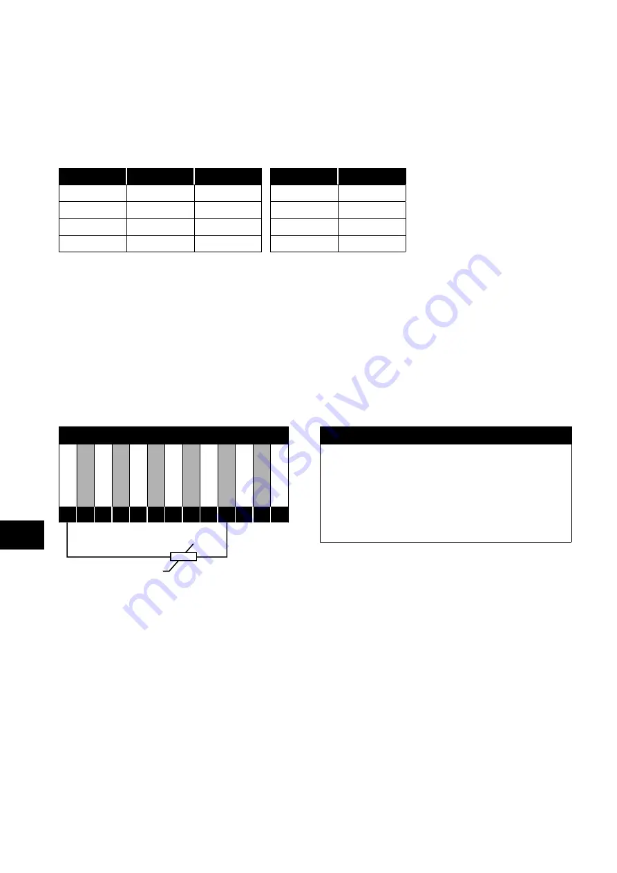
4.8.2. Motor Thermistor Connection
Where a motor thermistor is to be used, it should be connected as follows:
Motor Thermistor Connection
Additional Information
+2
4V DC
DI 1
DI 2
DI 3
+1
0V DC
AI 1
0V / C
OM
AO
1
0V / C
OM
AI 2
AO
2
ST
O
+
ST
O
-
Compatible Thermistor: PTC Type, 2.5kΩ trip level.
Use a setting of P1-13 that has Input 5 function as E-TRIP
“External Trip”, e.g. P1-13 = 6. Refer to section
Input Configuration Parameter P1-13
further details.
Enable the Motor PTC Thermistor Input function in parameter
P2-33.
1
2
3
4
5
6
7
8
9
10
11
12
13
4.9. Control Terminal Wiring
All analog signal cables should be suitably shielded. Twisted pair cables are recommended.
Power and Control Signal cables should be routed separately where possible, and must not be routed parallel to each other.
Signal levels of different voltages e.g. 24 Volt DC and 110 Volt AC, should not be routed in the same cable.
Maximum control terminal tightening torque is 0.5Nm.
Control Cable entry conductor size: 0.05 – 2.5mm2 / 30 – 12 AWG.
4
Elec
trical Installation


