


23
PROCEDURE 6
SEAT AND BACK
S
E
A
T
A
N
D
B
A
C
K
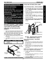
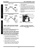
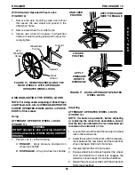
9000XDT (FIGURE 7)
NOTE: 9000XDT wheelchairs have two (2) frame
depth ranges; 16-18-inch and 19-20-inch. A 16-
18 frame depth wheelchair cannot be adjusted
to 19-20-inch and vice-versa.
1. Remove the existing seat upholstery from the
wheelchair. Refer to
REPLACING THE SEAT
UPHOLSTERY
in this procedure of the manual.
NOTE: When adjusting the seat depth of the
wheelchair, the seat upholstery MUST be
changed as well.
2. Remove the two (2) plug buttons from the ends
of the crossbraces that are towards the front of
the wheelchair.
NOTE: The two (2) plug buttons will be used in
the ends of the seat extension tubes.
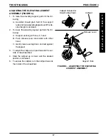
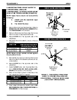
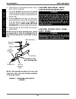
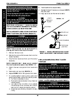
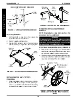
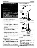
Seat
Extension
Spacer
Seat Upholstery
Plug Button
Seat Extension
Tube
Crossbrace
Use this hole for
2-inch Seat Extension
Use this hole for 1-inch
Seat Extension
FIGURE 6 - ADJUSTING SEAT DEPTH -
9000XT
5. Install the two (2) seat extension spacers onto
the two (2) seat extension tubes.
6. Secure the
NEW
seat upholstery to the
crossbaces. Refer to
REPLACING THE SEAT
UPHOLSTERY
in this procedure of the manual.
NOTE: Make sure to line up the mounting holes
in the seat extension tubes and seat extension
spacers with the NEW seat upholstery. Refer to
REPLACING THE SEAT UPHOLSTERY in this
procedure of the manual.
7. Install plug buttons into the ends of the seat ex-
tension spacers.
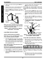
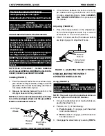
ADJUSTING SEAT DEPTH
9000XT Model (FIGURE 6)
1. Remove the existing seat upholstery from the
crossbraces. Refer to
REPLACING THE SEAT
UPHOLSTERY
in this procedure of the manual.
NOTE: When adjusting the seat depth of the wheel-
chair, the seat upholstery MUST be changed as
well.
2. Remove the two (2) plug buttons from the ends
of the crossbraces that are towards the front of
the wheelchair.
NOTE: The two (2) plug buttons will be used in
the ends of the seat extension spacers.
3. Install the two (2) seat extension tubes into the
ends on the crossbraces.
4. Perform one (1) of the following
A.
1-INCH SEAT EXTENSION -
Line up the
third
mounting hole from the
rear
of the seat
extension tube with the mounting hole in the
crossbrace. Repeat for opposite seat exten-
sion tube.
B.
2-INCH SEAT EXTENSION -
Line up the
second
mounting hole from the
rear
of the
seat extension tube with the mounting hole
in the crossbrace. Repeat for opposite seat
extension tube.
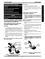
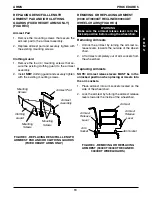
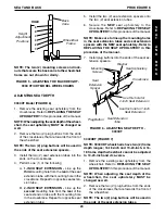
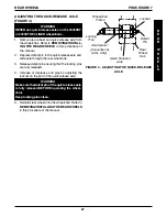
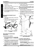
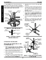
FIGURE 5 - ADJUSTING THE BACK HEIGHT -
9000 XT/XDT MODEL WHEELCHAIRS
NOTE: The two (2) mounting screws and lock-
nuts that secure the back cane to the wheelchair
frame are not shown for clarity.
Wheelchair
Frame
HOLE
6
5
4
3
2
1
Height
Adjustment
Positions
Back
Cane
Washer
Mounting
Screws
Summary of Contents for 9000 SL
Page 42: ...42 NOTES N O T E S NOTES...