background image

20

CONVERTING FROM SPACE SAVER TO
CONVENTIONAL ARMS OR
CONVENTIONAL TO SPACE SAVER ARMS
(9000 XT/XDT WHEELCHAIRS) (FIGURE 5)

NOTE: Space Saver arms do not work with the
following:

A.

9000XT with the adjustable angle
back option.

B.

The 9000XT Recliner.

1. Remove the arms from the wheelchair. Refer to

REMOVING OR REPLACING ARMRESTS

 in

this 

PROCEDURE

 of the manual.

2. Remove the locknut and hex screw that secure

the arm socket to the wheelchair frame.

3. Repeat 

STEP 2

 for the opposite side of the

wheelchair.

4. Reposition the arm socket to one (1) of two (2)

positions:

ARM TYPE

ARM SOCKET POSITION

(On wheelchair Frame)

Conventional

OUTSIDE

Space Saver

INSIDE

NOTE: Make sure arm sockets sit flush against
the wheelchair frame.

5. Reinstall the hex screw and locknut that secure

the arm socket to the wheelchair frame and se-
curely tighten.

6. Repeat 

STEP 5

 for the opposite side of the

wheelchair.

7. Install the 

NEW

 arms onto the wheelchair. Re-

fer to 

REMOVING OR REPLACING ARM-

RESTS

 in this section of the manual.

8. Refer to the following chart to determine if the

rear wheel axle spacer is needed:

WHEELCHAIR

AXLE SPACER

 USING

NEEDED?

Conventional Arms

YES

Space Saver Arms

NO

9. If rear wheel axle spacer is needed, refer to 

RE-

MOVING/INSTALLING THE REAR WHEELS

 in

PROCEDURE 7

 of this manual.

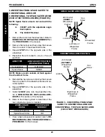
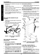
Arm Socket

(

INSIDE

 of

Wheelchair

Frame)

Hex

Screw

Locknut

Left Side of

Wheelchair

Frame

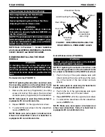
FIGURE 5 - CONVERTING FROM SPACE

SAVER TO CONVENTIONAL ARMS OR

CONVENTIONAL TO SPACE SAVER ARMS

(9000 XT/XDT WHEELCHAIRS)

Right Side of

Wheelchair

Frame

A
R

M

S

PROCEDURE 5

ARMS

SPACE SAVER ARM POSITION

CONVENTIONAL ARM POSITION

Hex

Screw

Locknut

Arm Socket

(

OUTSIDE

 of

Wheelchair

Frame)

Wheelchair

Frame

Summary of Contents for 9000 SL

Page 1: ...nd MAINTENANCE MANUAL 9000 SL 9000 XT 9000 XDT 9000XT RECLINER 9000 SERIES DEALER THIS MANUAL MUST BE GIVEN TO THE USER OF THE WHEELCHAIR USER BEFORE USING THIS WHEELCHAIR READ THIS MANUAL AND SAVE FO...

Page 2: ...ndividual rests solely with the user and his her healthcare profes sional capable of making such a selection WHEELCHAIR TIE DOWN RESTRAINTS AND SEAT RESTRAINTS Invacare recommends that wheelchair user...

Page 3: ...R CONVENTIONAL TO SPACE SAVER ARMS 9000 XT XDT WHEELCHAIRS 20 PROCEDURE 5 SEAT AND BACK 21 REPLACING THE SEAT UPHOLSTERY 21 REPLACING THE BACK UPHOLSTERY 21 ADJUSTINGTHEBACKHEIGHT 22 ADJUSTINGSEATDEPT...

Page 4: ...PERS 34 REMOVING INSTALLINGTHEREARWHEELS 34 USING ADJUSTINGTHEWHEELLOCKS 35 INSTALLING THE I V ROD HOLDER 36 INSTALLING THE TELESCOPING I V ROD SUPPORT TUBE 37 ADJUSTNG THE TELESCOPING I V ROD 37 PROC...

Page 5: ...chair requires the close attention of the wheelchair user as well as the assistant This manual points out the most common procedures and techniques involved in the safe op eration and maintenance of t...

Page 6: ...heelchair up against the first step while securely grasping a non removable non detachable part of the wheelchair for leverage 2 The second assistant with a firm hold on a non detachable part of the f...

Page 7: ...t with transfer During independent transfer little or no seat plat form will be beneath you Use a transfer board if at all possible PERCENTAGE OF WEIGHT DISTRIBUTION WARNING DO NOT attempt to reach ob...

Page 8: ...base Reach back only as far as your arm will extend without changing your sitting position FUNCTIONAL REACH FROM A WHEELCHAIR The approximate reach limit values shown in the accompanying graph were de...

Page 9: ...ntil the wheelchair is fully open 4 RECLINERS ONLY Secure the detached end of the spreader bar to the side frame Refer to STORING REPLACING THE SPREADER BAR in PROCEDURE 10 of this manual 5 Engage bot...

Page 10: ...ace Saver Conventional and Fixed Adjustable Height Desk Length Space Saver Fixed Height Arms Standard Swingaway Foot rests and Elevat ing Legrests SPECIFICATIONS 9000XT RE CLINER 23 25 27 28 29 or 31...

Page 11: ...e 50 1 2 lbs 60 1 2 lbs Rear Axle Rear Wheels Handrims Wheel Locks Caster Size Upholstery Frame Colors Weight Shipping Weight approx 9000XT Permanent Standard and Quick Release 20 22 and 24 inch Compo...

Page 12: ...etachable parts Lifting by means of any removable detach able parts of a wheelchair may result in injury to the user and or assistant or damage to the wheelchair DO NOT stand on the frame of the wheel...

Page 13: ...cks easy to engage X X SEAT AND BACK UPHOLSTERY PROCEDURE 6 Inspect for rips or sagging X X Inspect for loose or broken hardware X X TIRES PROCEDURES 7 and 8 Inspect for flat spots and wear X X X If p...

Page 14: ...d equal pressure X X X X Check for loose stem nuts and bolts X X X Check that both casters contact the ground at the same time T R O U B L E S H O O T I N G PROCEDURE 3 TROUBLESHOOTING MAINTENANCE M A...

Page 15: ...URE 4 F R O N T R I G G I N G S FIGURE 1 SWINGAWAY FOOTREST ASSEMBLY INSTALLATION Hinge Pins Swingaway Footrest Assembly Hinge Plate Footrest Release Lever Hinge Plate Removing 1 Push the footrest rel...

Page 16: ...5 ELEVATING LEGREST ASSEMBLY INSTALLATION Lower Footrest Assembly Footplate Calfpad Assembly Bolt and Locknut Hinge Plates Legrest Release Handle Hinge Pins STEP 1 STEPS 2 AND 3 FIGURE 4 HEEL LOOP REP...

Page 17: ...1 hand B Push release lever downward with other hand C Gently lower user leg down and rest against the legrest F R O N T R I G G I N G S PROCEDURE 4 FRONT RIGGINGS 3 To adjust the calfpad turn pad to...

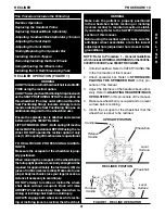
Page 18: ...ing Adjusting Armrest Height Swing Back Arms Replacing Desk Full Length Armrest Pad and or Clothing Guards Fixed Height Arms Only Removing or Replacing Armrest 9000 XT 9000XT RECLINER 9000XDT Wheelcha...

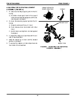
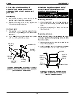
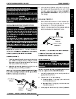
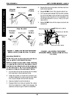
Page 19: ...using the wheelchair Removing Armrests 1 Unlock the armrest by turning the armrest re lease levers towards the outside of the wheel chair 2 Lift armrest completely out of arm sockets from the wheelch...

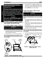
Page 20: ...x screw and locknut that secure the arm socket to the wheelchair frame and se curely tighten 6 Repeat STEP 5 for the opposite side of the wheelchair 7 Install the NEW arms onto the wheelchair Re fer t...

Page 21: ...ounting Screws REPLACING THE BACK UPHOLSTERY Screw On Back Upholstery 9000 SL FIGURE 2 1 Flip swing back arms up and out of the way Refer to SWING BACK ARMS in PROCEDURE 5 of this manual 2 Remove the...

Page 22: ...the back canes to one 1 of five 5 height adjustment positions Original Back Height in inches KHOLE 1 2 2 3 3 4 4 5 5 6 HEIGHT 15 16 17 18 19 K Holes numbered from bottom to top for refer ence only Th...

Page 23: ...upholstery Refer to REPLACING THE SEAT UPHOLSTERY in this procedure of the manual 7 Install plug buttons into the ends of the seat ex tension spacers ADJUSTING SEAT DEPTH 9000XT Model FIGURE 6 1 Remo...

Page 24: ...DJUSTING BACK ANGLE 9000XT ADJUSTABLE BACK MODEL ONLY WARNING The back angle and seat depth directly relate to the stability of the wheelchair Any change to one 1 or any combination of the two 2 may c...

Page 25: ...NOTE Axle spacer is used only if wheelchair is equipped with conventional arms 2 Repeat STEP 1 for the opposite rear wheel 3 To reinstall the rear wheel onto the wheelchair reverse STEPS 1 2 NOTE Mak...

Page 26: ...cedure of the manual 6 If the locking pins of the quick release axles if applicable are not protruding past the inside of the axle bushing or there is too much move ment of the rear wheel assembly in...

Page 27: ...at the locking pins are fully released 4 Increase or decrease end play by adjusting the locknut on the end of the quick release axle WARNING Make sure the detent pin of the quick release axle is fully...

Page 28: ...rk 5 Reassemble by reversing STEPS 1 3 6 Repeat STEPS 1 5 for the opposite front caster 7 To properly tighten caster journal system and guard against flutter perform the following check a Tip back of...

Page 29: ...NOTE A 1 1 2 to 2 inch clearance between the bot tom of the anti tipper wheels and the ground floor MUST be maintained at all times W H E E L L O C K S A N T I T I P P E R S 3 If the distance between...

Page 30: ...e also an option on the 9000XT Recliner NOTE If wheels are pneumatic before adjusting or replacing the wheel lock assemblies ensure that the tires are inflated to the recommended psi on the side wall...

Page 31: ...twenty 20 de grees of incline reverse recline Make sure to use proper body mechanics use your legs or seek as sistance if necessary to avoid injury DO NOT attempt to recline or incline the wheel chai...

Page 32: ...illow Refer to REPLACING THE HEADREST PILLOW in this PROCEDURE of the manual 2 Remove the six 6 mounting screws that secure the headrestupholsterytotheheadrestextensiontubes 3 Secure NEW headrest upho...

Page 33: ...the recliner tube REMOVING FROM THE STORED POSITION 1 Rotate the end of the spreader bar 90 o toward the opposite side frame 2 Install threaded end of locking knob into locknut located on the opposite...

Page 34: ...g until the bottom release button locks in place PROCEDURE 10 RECLINER Spacers Axle Mounting Screw Patient Operated Wheel Lock Rear Wheel Wheelchair Frame Locknut FIGURE9 REMOVING INSTALLINGTHEREAR WH...

Page 35: ...lated to the recommended psi located on the side wall of tire 1 Loosen the bolt and locknut that secure the wheel lock to the recliner tube 2 Adjust the position of wheel lock until the measure ment b...

Page 36: ...et STEP 3 Pivot Screw STEP 4 Back Tube STEP 3 Locknut STEP 6 Mounting Screw STEP 6 I V Holder STEP 4 Locknut STEPS 3 5 OPTIONS FOR THE RECLINER INSTALLING THE TELESCOPING I V ROD HOLDER FIGURE 13 1 Re...

Page 37: ...ghten NOTE The large nylon washer must be inserted into hole and pressed in so that it is flush with outside surface of rear cylinder RECLINER PROCEDURE 10 R E C L I N E R 4 Reinstall the rear wheel f...

Page 38: ...10 for 9000XT Recliner options NOTE Refer to Procedure 1 General Guidelines whichincludeGENERALWARNINGSforthe9000SL 9000XT 9000XDT and 9000XT RECLINER INSTALLING THE TELESCOPING I V ROD O2 HOLDERS FI...

Page 39: ...at secures the base to the step tube of the wheelchair 4 Remove the upper back upholstery screw and washer 5 Align the strap with the back upholstery screw mounting hole 6 Reinstall the back upholster...

Page 40: ...racket on wheelchair ADULT A DOWN RIGHT TOP ADULT B DOWN LEFT TOP HEMI B UP RIGHT BOTTOM HEMI A UP LEFT BOTTOM K A and B are stamped on the sides of the amputee bracket 2 Install the amputee bracket o...

Page 41: ...ee bracket on the wheelchair frame to the position determined in STEP 1 NOTE Make sure the axle spacer is pointing towards the outside of the wheelchair 3 Install the two 2 hex screws and locknuts tha...

Page 42: ...42 NOTES N O T E S NOTES...

Page 43: ...di cate nature of the defect and if the product is serialized indicate the serial number Do not return products to our factory without our prior consent LIMITATIONS AND EXCLUSIONS THE FOREGOING WARRAN...

Page 44: ...INVACARE CORPORATION ONE INVACARE WAY Elyria OH 44035 Customer Service 800 333 6900 Technical Support 800 832 4707 Form No 95 138 Part No 1056953 Rev E 1 4 99 Printed in USA...

Page 45: ...Invacare Australia 1 Lenton Place North Rocks NSW 2151 Australia www invacare com au email sales invacare com au Phone 1800 460 460 Fax 02 8839 5311...

Reviews: