


Intel® Server Board SE7520AF2 TPS
Integrated Intel® RAID Controller SROMBU42E
Revision 1.2
87
Intel order number C77866-003
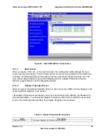
Drive coercion refers to the ability of the controller to recognize the size of the physical
drives that are connected and then force the larger drives to use only the amount of
space available on the smallest drive. Drive coercion as implemented in these RAID
controllers also allows an option to map out a reserved space to compensate for slightly
smaller drive sizes that may be added later. This option allows 16 MB, 256 MB, and 1
GB of drive capacity to remain unused.
A pulled drive will go to a not responding state if there is no I/O. Not responding is a
virtual state, not a persistent state. It is the state that applications will report when
management I/O to the drive fails.
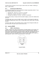
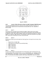
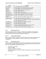
4.3.2
RAID Level Migration
Table 33. RAID Level Migration Matrix
0
1
5
0 ->
N/A
Yes, though OCE
Yes, through OCE
1 ->
Yes
N/A
Yes, through OCE
5
-> Yes No
N/A
4.3.3
Fault Tolerant Features
Array configuration information is stored both on the hard drive (COD) and in NVRAM. This
helps protect against loss of the configuration due to adapter and/or drive failure. Failed drives
are automatically detected and a transparent rebuild of the failed drive automatically occurs
using hot spare drives.
Support for SAF-TE enabled enclosures allows enhanced drive failure and rebuild reporting via
enclosure LEDs; support also includes hot swapping of hard drives.
Battery backup for cache memory is available as an option for some controllers. RAID controller
firmware automatically checks for the presence of the battery module, and if found, allows the
write back cache option. The adapter continuously tracks the battery voltage and reports if the
battery is low. When low, the battery is first given a fast charge to replenish the charge and is
then given a trickle charge to keep the battery at an optimal power level. Adapters that support
the battery module include a “dirty cache” LED; when power is lost to the system and data
remains in the cache memory that has not been written to disk, this LED signals that this
operation needs to be completed. Upon reboot, the data in memory can then be written out to
disk.
SMART technology is also supported, which provides a higher level of predictive failure analysis
of the hard disk drives by the RAID controller.
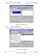
4.3.4
Cache Options and Settings
Cache options and settings can be unique for each logical drive.
Cache Write Policy
Write Through - I/O completion is signaled only after the data is written to hard disk.


