


Connectors, Headers and Jumpers
Intel® Server Board SE7520AF2 TPS
232
Revision
1.2
Intel order number C77866-003
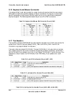
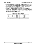
Pin
Side B
Side A
Pin
Side B
Side A
24 AD[25]
Ground
70 +3.3
V
AD[60]
25 +3.3
V
AD[24]
71 AD[59]
AD[58]
26 C/BE[3]#
IDSEL
72 AD[57]
Ground
27 AD[23]
+3.3
V
73 Ground
AD[56]
28 Ground
AD[22]
74 AD[55] AD[54]
29
AD[21] AD[20] 75
AD[53] +3.3
V
30 AD[19]
Ground
76 Ground
AD[52]
31 +3.3
V
AD[18]
77 AD[51]
AD[50]
32 AD[17]
AD[16] 78
AD[49] Ground
33 C/BE[2]#
+3.3V
79 +3.3
V
AD[48]
34 Ground
FRAME#
80 AD[47]
AD[46]
35 IRDY#
Ground
81 AD[45]
Ground
36 +3.3
V
TRDY#
82 Ground
AD[44]
37 DEVSEL#
Ground
83 AD[43]
AD[42]
38 PCIXCAP
STOP#
84 AD[41]
+3.3
V
39 LOCK#
+3.3
V
85 Ground
AD[40]
40 PERR#
SMBUS
SCL 86 AD[39]
AD[38]
41
+3.3 V
SMBUS SDA
87
AD[37]
Ground
42
SERR# Ground 88
+3.3
V AD[36]
43 +3.3
V
PAR
89 AD[35]
AD[34]
44 C/BE[1]#
AD[15] 90
AD[33] Ground
45 AD[14]
+3.3
V
91 Ground
AD[32]
46 Ground
AD[13]
92 Riser
Presence1 Riser
Presence2
47
AD[12] AD[11] 93
Upper Slot
REQ# GND
48 AD[10]
Ground
94 Ground
Upper
Slot
GNT#
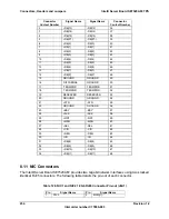
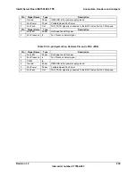
8.8 Front Panel Connectors
A standard SSI 34-pin header is provided to support a system front panel. The header contains
reset, NMI, power control buttons, and LED indicators. The following tables detail the pin outs of
the header.
Table 125. Front Panel 34-Pin Header Pin-out (J1E1)
Pin
Signal Name
Pin
Signal Name
1
Power LED Anode
2
5VSB
3
Key
4
Fan Fail LED Anode
5
Power LED Cathode
6
Fan Fail LED Cathode
7
HDD Activity LED Anode
8
Power Fault LED Anode
9
HDD Activity LED Cathode
10
Power Fault LED Cathode
11
Power Switch
12
NIC1 Activity LED Anode
13
GND (Power Switch)
14
NIC1 Activity LED Cathode


