


Connectors, Headers and Jumpers
Intel® Server Board SE7520AF2 TPS
238
Revision
1.2
Intel order number C77866-003
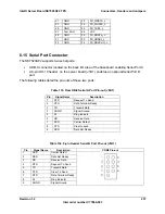
8.16 Keyboard and Mouse Connector
Two stacked PS/2* ports are provided in a single housing for keyboard and mouse support.
Although the board set supports swapping of these connections, the top port is color-coded
green to designate mouse support, and the bottom port is color-coded violet to designate
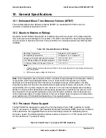
keyboard support. The following table details the pin-out of the PS/2 connectors.
Table 135. Keyboard and Mouse PS2 Connector Pin-out (J9A1)
Keyboard
Mouse
Pin
Signal Name
Pin
Signal Name
1 KBDATA 1 MSDATA
2 N/C 2 N/C
3 GND 3 GND
4
Fused 5V
4
Fused 5V
5 KBCLK 5 MSCLK
6 N/C 6 N/C
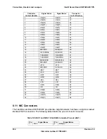
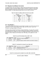
8.17 Fan Headers
The Intel® Server Board SE7520AF2 provides eight fan headers: two for CPU fans and six for
system fans. The CPU fans are labeled “CPU1_FAN” and “CPU2_FAN”. The CPU fan
connectors only support steady 12-volt power.
The system fans are labeled “SYS FAN_1” through “SYS FAN_6”. All system fan connectors
have variable speed control and are capable of supporting variable speed fans. “SYS FAN_1”
and “SYS FAN_2” are enabled via a 3-pin + 2-pin header; “SYS FAN_3” and SYS FAN_4” are
enabled via a 6-pin header; and “SYS FAN_5” and “SYS FAN_6” are enabled via a 3-pin
header.
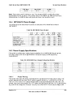
Table 136. 3-pin CPU Fan Headers Pin-out (J6F1, J5F1)
Pin
Signal Name
Type
Description
1
Ground
Power
GROUND is the power supply ground
2
Fan Power
Power
Straight 12V
3
Fan Tach
Out
FAN_TACH signal is connected to the BMC to monitor the FAN speed
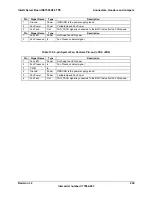
Table 137. 3 pin System Fan Headers Pin-out (J5A2, J5A1)
Pin
Signal Name
Type
Description
1
Ground
Power
GROUND is the power supply ground
2
Fan Power
Power
Variable Speed Fan Power
3
Fan Tach
Out
FAN_TACH signal is connected to the BMC to monitor the FAN speed
Table 138. 3+2 pin System Fan Headers Pin-out (J2J3+J2K3, J2J2+J2K1)


