


Intel® Server Board SE7520AF2 TPS
System BIOS
Revision 1.2
117
Intel order number C77866-003
The BIOS initializes and supports ATAPI devices such as LS-120/240, CD-ROM, CD-RW and
DVD. The BIOS initializes and supports SATA devices just like P-ATA devices. The BIOS
initializes embedded IDE controller in the chipset and SATA devices that are connected to these
controllers. From a software standpoint, SATA controllers present the same register interface as
the P-ATA controllers. The BIOS utilizes additional SATA capabilities to speed drive detection.
Hot plugging of SATA drives during the boot process is not supported by the BIOS and may
result in undefined behavior.
5.5.13
Removable Media Initialization
The BIOS supports removable media devices, including 1.44MB floppy removable media
devices and optical devices such as a CD-ROM drive or DVD-ROM drive (read only). The BIOS
supports booting from USB mass storage devices connected to the chassis USB port, such as a
USB key device.
The BIOS supports USB 2.0 media storage devices that are backward compatible to the
Universal Serial Bus Specification, Revision 1.1.
5.6 Flash
ROM
The BIOS supports the Intel
®
28F320C3B flash part. The flash part is a 4 MB flash ROM, 2 MB
of which is programmable. The flash ROM contains system initialization routines, setup utility,
and runtime support routines. The exact layout is subject to change, as determined by Intel. A
128 KB block is available for storing OEM code (user binary) and custom logos.
5.7 BIOS User Interface
Two types of consoles are used to display the user interface: graphical or text based. Graphics
consoles are in 640x480 mode; text consoles are 80x25.
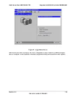
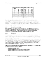
Console output is partitioned into three areas: the System Activity/State, Logo/Diagnostic, and
Current Activity windows. The System Activity Window displays information about the current
state of the system, such as if it is active, hung, or requires user intervention. The
Logo/Diagnostic Window displays the OEM splash screen logo or a diagnostic boot screen. The
Current Activity Window displays information about the currently executing portion of POST as
well as user prompts or status messages.
System State Window
Current Activity Window
Logo/Diagnostic Window
Figure 34. BIOS Screen Display Areas


