


Intel® Server Board SE7520AF2 TPS
Connectors, Headers and Jumpers
Revision 1.2
227
Intel order number C77866-003
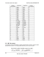
FMC Signal Name
FMC Pin
Description
CPU1_SKTOCC_N
82
Indicates that a processor is in the primary processor socket. If this
socket is detected empty and there’s an attempt to power up the
system, the IMM will output an Error Beep Code and prevent the
System from turning on
IMM_SOUT
85
EMP/SOL Serial Data Out. This is the Serial Port data output from
IMM and should be connected to the SIN signal in the SIO3 device
IMM_SIN
86
EMP/SOL Serial Data In. This is the Serial Port data input into the
IMM and should be connected to the SOUT signal in the SIO3 device
IMM_DCD_N
87
EMP/SOL Data Carrier Detect. This is the Serial Port Data Carrier
Detect input into the IMM and should be connected to the DCD signal
in the SIO3 device
IMM_RTS_N
88
EMP/SOL Request to Send. This is the Serial Port Request to Send
output from IMM and should be connected to the CTS (Clear to Send)
signal in the SIO3 device
IMM_DTR_N
89
EMP/SOL Data Terminal Ready. This is the Serial Port Data Terminal
Ready output from IMM and should be connected to the DSR (Data
Set Ready) signal in the SIO3 device
IMM_CTS_N
90
EMP/SOL Clear to Send. This is the Serial Port Clear to Send input
into the IMM and should be connected to the RTS (Ready to Send)
signal in the SIO device
ICMB_RX
93
Inter Chassis Communication Management Bus receive data
ICMB_TX
94
Inter Chassis Communication Management Bus transmit data
ICMB_TX_EN
96
Inter Chassis Communication Management Bus transceiver enable
IMM_RI_BUF_N
97
Ring Indicator from the EMP serial port on the baseboard
RST_PWRGD_PS
101
Power good signal from power subsystem. In typical system, this
signal is connected to PWR_OK signal on power supply. This signal
is monitored by the IMM to detect a Power Supply failure
LAN_SMBALERT_N
102
Alert signal from the motherboard NIC (LOM).
ICH_SLP_S4_N
103
Power Off request from the Chipset
ICH_SMI_BUFF_N
105
SMI signal from Chipset. This signal is monitored by the IMM to
detect an “SMI Time-out” condition. If this signal is asserted for longer
than a predefined SMI Time-out timer, an event is logged and the
IMM interrogates the chipset for further data, such as fatal errors.
CHPSET_ERR_ALERT_N 106
When available from chipset, indicates that a error occurred and IMM
will need interrogate Chipset for further data, such as fatal errors. If
not available, leave as NC.
FP_RST_BTN_N
109
Front panel Reset Button input.
ICH_RST_BTN_N
110
Passthrough of front panel Reset button to the chipset. IMM chassis
control command will also use this.
FP_PWR_BTN_N
113
Front panel power button input.
IMM_IRQ_SMI_N
116
IMM might use this signal to generate an SMI to the system.
IMM_PRES_N
120
When IMM is present, this signal is asserted. This signal can be used
to notify BIOS that a module is present (via routing to GPIO), as well
as to control any logic which behaves differently when IMM is present,
such as the FML mux (if supported), etc
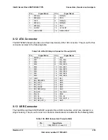
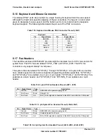
8.6.2 ICMB
Header
Table 117. ICMB Header Pin-out (J1A1)


