


Functional Architecture
Intel® Server Board SE7520AF2 TPS
68
Revision
1.2
Intel order number C77866-003
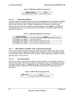
Table 22. NIC2 Status LED
LED Color
LED State
NIC State
Off
10 Mbps
Green
100 Mbps
Green/Amber (Right)
Amber 1000
Mbps
On
Active Connection
Green (Left)
Blinking
Transmit / Receive activity
3.4.9
USB 2.0 Support
The Intel® Server Board SE7520AF2 uses the USB 2.0 functionality integrated into ICH5-R.
This supports up to six USB ports. The server board utilizes five of these ports: three ports are
located on the back edge of the board, and two are available internally via a DH-10 connector
that can be routed to the front of the chassis. The front USB ports can be disabled through the
BIOS Setup Utility.
3.4.10 Super
I/O
Legacy I/O support is provided by using a National Semiconductor* PC87427 Super I/O device.
This chip contains the necessary circuitry to control two serial ports, a floppy disk drive, and
PS/2-compatible keyboard and mouse. The Intel® Server Board SE7520AF2 supports the
following features:
General Purpose Input/Output (GPIO)
Two serial ports
Floppy controller
Keyboard and mouse controller
Wake up control
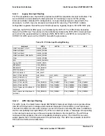
3.4.10.1 General Purpose Input/Output (GPIO)
The National Semiconductor* PC87427 Super I/O provides general-purpose input/output pins
that the Intel® Server Board SE7520AF2 utilizes. The following table identifies the pins and the
signal names used in the schematic:
Table 23. Super I/O GPIO Usage Table
Pin
Name
IO/GPIO
Intel® Server Board SE7520AF2 Use
50
LED1
Output
FP Power LED
82 LMPCIF
Input/Output Single
wire temperature sensor for PWM2
54
WDO_N
Output
Rolling BIOS Reset
124 GPIO00
Input/Output Manufacturing Detect Mode
10
GPIO6
Input/Output
BMC SYS IRQ
13 GPIO7/HFCKOUT
Input/Output Available
37 GPIO27/SIOSMI Input/Output SIO
SMI
21
GPIOE40
Input/Output
Riser Detect 1


