Reference Thermal Solution
22
Thermal and Mechanical Design Guidelines
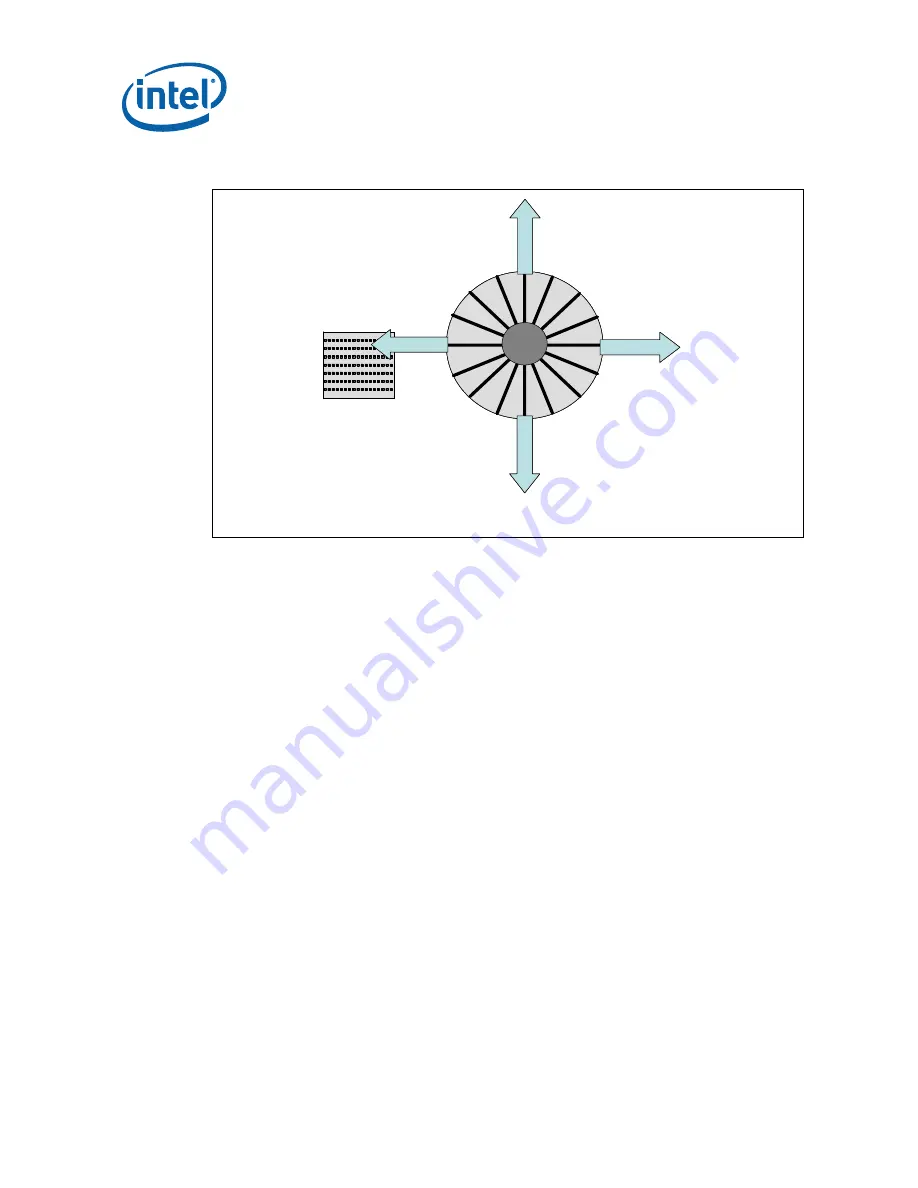
Figure 7. Processor Heatsink Orientation to Provide Airflow to GMCH Heatsink on an
ATX Platform
Airflow Direction
A
irf
lo
w
D
ir
e
c
tio
n
Airflow Direction
A
irf
lo
w
D
ir
e
c
tio
n
GMCH Heatsink
Omni Directional Flow
Processor Heatsink
(Fan not Shown)
TOP VIEW
Airflow Direction
A
irf
lo
w
D
ir
e
c
tio
n
Airflow Direction
A
irf
lo
w
D
ir
e
c
tio
n
GMCH Heatsink
Omni Directional Flow
Processor Heatsink
(Fan not Shown)
TOP VIEW
Other methods exist for providing airflow to the GMCH heatsink, including the use of
system fans and/or ducting, or the use of an attached fan (active heatsink).
4.1.2
Balanced Technology Extended (BTX) Form Factor
Operating Environment
This section provides operating environment conditions based on what has been
exhibited on the Intel micro-BTX reference design. On a BTX platform, the GMCH
obtains in-line airflow directly from the processor thermal module. Since the processor
thermal module provides lower inlet temperature airflow to the processor, reduced
inlet ambient temperatures are also often seen at the GMCH as compared to ATX. An
example of how airflow is delivered to the GMCH on a BTX platform is shown in
The local ambient air temperature, T
A
, at the GMCH heatsink in the Intel micro-BTX
reference design is predicted to be ~45 °C. The thermal designer must carefully select
the location to measure airflow to get a representative sampling. These environmental
assumptions are based on a 35 °C system external temperature measured at sea
level.
Note:
The local ambient air temperature is based on the power for a 2005 platform,
processor with a TDP up to 130 W.
Note:
The risk of the solder ball fracture can be minimized with good chassis structure
design on a BTX platform, refer to the
Balanced Technology Extended (BTX) Chassis
Design Guide (or Balanced Technology Extended (BTX) System Design Guide)
for
detailed chassis mechanical design.
Summary of Contents for 82G35
Page 6: ...6 Thermal and Mechanical Design Guidelines...
Page 10: ...Introduction 10 Thermal and Mechanical Design Guidelines...
Page 16: ...Product Specifications 16 Thermal and Mechanical Design Guidelines...
Page 20: ...Thermal Metrology 20 Thermal and Mechanical Design Guidelines...
Page 30: ...Mechanical Drawings 30 Thermal and Mechanical Design Guidelines Figure 11 GMCH Package Drawing...


