


Case Temperature Reference Metrology
R
82
Thermal/Mechanical Design Guide
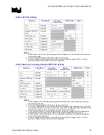
8.
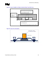
Place the processor under the microscope unit (similar to the one used in Figure 36) to
continue with the process. It is also recommended to use a fixture (like a processor tray or a
plate) to help hold the unit in place for the rest of the attach process.
9.
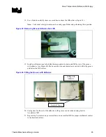
Press the wire down about 6 mm [0.125”] from the thermocouple bead using the tweezers.
Look in the microscope to perform this task. Place a piece of Kapton tape to hold the wire
inside the groove (Figure 33). Refer to Figure 34 for detailed bead placement.
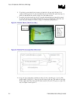
Figure 33. Position Bead on the Groove Step
Figure 34. Detailed Thermocouple Bead Placement
10.
Using the micromanipulator, install the needle near to the end of the groove on top of the
thermocouple. Using the X, Y, and Z axes on the arm place the tip of the needle on top of the
thermocouple bead. Press down until the bead is seated at the end of the groove on top of the
step (see Figure 34 and Figure 35).
Wire section
into the
groove to
prepare for
final bead
placement
Kapton* tape
Summary of Contents for 640 - Pentium 4 640 3.2GHz 800MHz 2MB Socket 775 CPU
Page 14: ...Introduction R 14 Thermal Mechanical Design Guide ...
Page 38: ...Thermal Management Logic and Thermal Monitor Feature R 38 Thermal Mechanical Design Guide ...
Page 52: ...Intel Thermal Mechanical Reference Design Information R 52 Thermal Mechanical Design Guide ...
Page 60: ...Acoustic Fan Speed Control R 60 Thermal Mechanical Design Guide ...
Page 72: ...Heatsink Clip Load Metrology R 72 Thermal Mechanical Design Guide ...
Page 99: ...Mechanical Drawings R Thermal Mechanical Design Guide 99 Figure 50 Reference Fastener Sheet 1 ...
Page 103: ...Mechanical Drawings R Thermal Mechanical Design Guide 103 Figure 54 Clip Heatsink Assembly ...


