


Case Temperature Reference Metrology
R
Thermal/Mechanical Design Guide
83
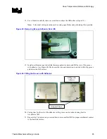
Figure 35. Using 3D Micromanipulator to Secure Bead Location
11.
Measure resistance from thermocouple end wires (hold both wires to a DMM probe) to the
IHS surface. This should be the same value as measured during the thermocouple
conditioning see Section D.6.1, step 2 and Figure 36.
Figure 36. Measuring Resistance between Thermocouple and IHS
12.
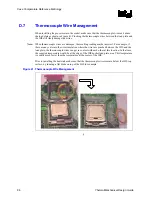
Place a small amount of Loctite 498 adhesive in the groove where the bead is installed. Using
a fine point device, spread the adhesive in the groove around the needle, the thermocouple
bead and the thermocouple wires already installed in the groove during step 5 above. Be
careful not to move the thermocouple bead during this step (Figure 37).
Summary of Contents for 640 - Pentium 4 640 3.2GHz 800MHz 2MB Socket 775 CPU
Page 14: ...Introduction R 14 Thermal Mechanical Design Guide ...
Page 38: ...Thermal Management Logic and Thermal Monitor Feature R 38 Thermal Mechanical Design Guide ...
Page 52: ...Intel Thermal Mechanical Reference Design Information R 52 Thermal Mechanical Design Guide ...
Page 60: ...Acoustic Fan Speed Control R 60 Thermal Mechanical Design Guide ...
Page 72: ...Heatsink Clip Load Metrology R 72 Thermal Mechanical Design Guide ...
Page 99: ...Mechanical Drawings R Thermal Mechanical Design Guide 99 Figure 50 Reference Fastener Sheet 1 ...
Page 103: ...Mechanical Drawings R Thermal Mechanical Design Guide 103 Figure 54 Clip Heatsink Assembly ...


