


Heatsink Clip Load Metrology
R
Thermal/Mechanical Design Guide
69
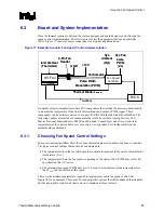
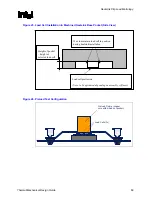
Figure 25. Load Cell Installation in Machined Heatsink Base Pocket (Side View)
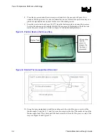
Figure 26. Preload Test Configuration
Load Cells (3x)
Preload Fixture (copper
core with milled out pocket)
Wax to maintain load cell in position
during heatsink installation
Height of pocket
~ height of
selected load cell
Load cell protrusion
(Note: to be optimized depending on assembly stiffness)
Summary of Contents for 640 - Pentium 4 640 3.2GHz 800MHz 2MB Socket 775 CPU
Page 14: ...Introduction R 14 Thermal Mechanical Design Guide ...
Page 38: ...Thermal Management Logic and Thermal Monitor Feature R 38 Thermal Mechanical Design Guide ...
Page 52: ...Intel Thermal Mechanical Reference Design Information R 52 Thermal Mechanical Design Guide ...
Page 60: ...Acoustic Fan Speed Control R 60 Thermal Mechanical Design Guide ...
Page 72: ...Heatsink Clip Load Metrology R 72 Thermal Mechanical Design Guide ...
Page 99: ...Mechanical Drawings R Thermal Mechanical Design Guide 99 Figure 50 Reference Fastener Sheet 1 ...
Page 103: ...Mechanical Drawings R Thermal Mechanical Design Guide 103 Figure 54 Clip Heatsink Assembly ...


