


Heatsink Clip Load Metrology
R
68
Thermal/Mechanical Design Guide
Note:
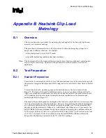
When optimizing the heatsink pocket depth, the variation of the load cell height should also be
taken into account to make sure that all load cells protrude equally from the heatsink base. It may
be useful to screen the load cells prior to installation to minimize variation.
Remarks: Alternate Heatsink Sample Preparation
As just mentioned, making sure that the load cells have minimum protrusion out of the heatsink
base is paramount to meaningful results. An alternate method to make sure that the test setup will
measure loads representative of the non-modified design is:
•
Machine the pocket in the heat sink base to a depth such that the tips of the load cells are just
flush with the heat sink base.
•
Then machine back the heatsink base by around 0.25 mm [0.01”], so that the load cell tips
protrude beyond the base.
Proceeding this way, the original stack height of the heatsink assembly should be preserved. This
should not affect the stiffness of the heatsink significantly.
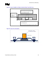
Figure 24. Load Cell Installation in Machined Heatsink Base Pocket (Bottom View)
Package IHS
Outline (Top
Surface)
Load Cells
Heatsink Base Pocket
Diameter ~ 29 mm
[~1.15”]
Summary of Contents for 640 - Pentium 4 640 3.2GHz 800MHz 2MB Socket 775 CPU
Page 14: ...Introduction R 14 Thermal Mechanical Design Guide ...
Page 38: ...Thermal Management Logic and Thermal Monitor Feature R 38 Thermal Mechanical Design Guide ...
Page 52: ...Intel Thermal Mechanical Reference Design Information R 52 Thermal Mechanical Design Guide ...
Page 60: ...Acoustic Fan Speed Control R 60 Thermal Mechanical Design Guide ...
Page 72: ...Heatsink Clip Load Metrology R 72 Thermal Mechanical Design Guide ...
Page 99: ...Mechanical Drawings R Thermal Mechanical Design Guide 99 Figure 50 Reference Fastener Sheet 1 ...
Page 103: ...Mechanical Drawings R Thermal Mechanical Design Guide 103 Figure 54 Clip Heatsink Assembly ...


