Intel® Thermal/Mechanical Reference Design Information
R
46
Thermal/Mechanical Design Guide
5.6
ATX Reference Thermal Mechanical Solution for the
Intel
®
Pentium
®
4 Processor in the 775–Land LGA
Package
The reference thermal solution is an active air-cooled design, with a fan installed at the top of the
heatsink. This solution is called the Intel
®
Radial Curved Bifurcated Fin Heatsink Reference
Design (Intel
®
RCBFH-3 Reference Design).
The reference solution is compliant with the reference ATX motherboard keep-out and height
recommendations defined in Section 5.5.
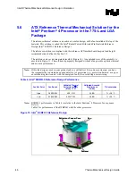
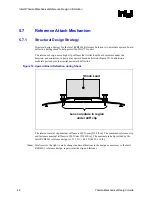
The solution comes as an integrated assembly (Figure 10). An exploded view of the assembly is
provided in Figure 11. The solution is purposely designed without a fan guard to optimize thermal
and acoustic performance.
Note:
If this fan design is used in your product and you will deliver it to end use customers, you have
the responsibility to determine an adequate level of protection (e.g., protection barriers, a cage, or
an interlock) against contact with the energized fan by the user during user servicing.
Table 4. Intel
®
RCBFH-3 Reference Design Performance
Fan Set Point
Fan Speed
Validated Thermal
Performance
Ψ
ca
(Mean + 3
σ
)
Validated Acoustic
Performance
(LwAd)
T
A
Assumption
High 3600
RPM 0.29
°
C/W 5.5
BA
T
A
= 38
°
C
Low 2400
RPM 0.325
°
C/W 4.5
BA
T
A
= 30
°
C
Note:
RCBFH-3 performance in Table 4 is relative to the Intel Pentium
®
4 Processor 5xx sequence.
Refer to
Table 2 for performance of the RCBFH-3 with the other processors.
Figure 10. Intel
®
RCBFH-3 Reference Design
Fan
Ext Copper Core
Fastener
Clip
Fan
Ext Copper Core
Fastener
Clip
Summary of Contents for 640 - Pentium 4 640 3.2GHz 800MHz 2MB Socket 775 CPU
Page 14: ...Introduction R 14 Thermal Mechanical Design Guide ...
Page 38: ...Thermal Management Logic and Thermal Monitor Feature R 38 Thermal Mechanical Design Guide ...
Page 52: ...Intel Thermal Mechanical Reference Design Information R 52 Thermal Mechanical Design Guide ...
Page 60: ...Acoustic Fan Speed Control R 60 Thermal Mechanical Design Guide ...
Page 72: ...Heatsink Clip Load Metrology R 72 Thermal Mechanical Design Guide ...
Page 99: ...Mechanical Drawings R Thermal Mechanical Design Guide 99 Figure 50 Reference Fastener Sheet 1 ...
Page 103: ...Mechanical Drawings R Thermal Mechanical Design Guide 103 Figure 54 Clip Heatsink Assembly ...


