


‑135‑
Note
●
Take the process in which motor decelerates from 3000 RPM to 0 RPM as an
example, suppose the load inertia is N times the motor inertia, then the braking
energy is (N+1) x E
O
when the motor decelerates from 3000 RPM to 0 RPM, and the
energy consumed by the regenerative resistor is (N+1) x E
O
‑ E
C
(E
C
represents the
energy absorbed by the capacitor). Suppose the reciprocating cycle is T, then the
power of the regenerative resistor needed is 2 x [(N + 1) x E
O
‑ E
C
]/T. For values of
E
O
and E
C
, see section "Parameter Settings" in SV660P Series Servo Drive
Commissioning Guide.
●
Determine whether to use the regenerative resistor according to the preceding
figure and select a built‑in or an external one as needed. Then, set H02‑25
accordingly.
●
The resistor with aluminum casing is recommended.
☆Related parameters
Para. No.
Name
Value Range
Description
Setting
Condition
Effective
Time
Default
H02‑25
Regenerative
resistor type
0: Built‑in
1: External, natural cooling
2: External, forced air
cooling
3: No resistor needed,
braking energy absorbed by
the capacitor only
Defines the
regenerative resistor
type and the mode of
absorbing and
releasing the braking
energy.
At stop
Immediately
0
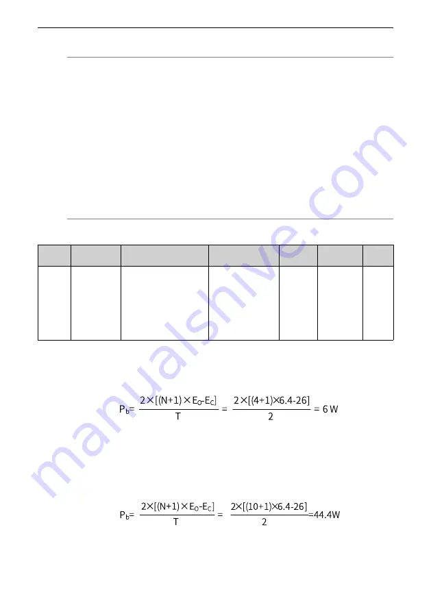
Take the H1 series 750 W model as an example. Suppose the reciprocating cycle (T) is
2s, the maximum speed is 3000 RPM, and the load inertia is 4 times the motor inertia,
the required power of the regenerative resistor is as follows:
The calculated result is smaller than the processing capacity (P
a
= 25 W) of the built‑in
regenerative resistor, so a built‑in regenerative resistor is sufficient.
If the inertia ratio in the preceding example is changed to 10 times the motor inertia,
and other conditions remain the same, the required regenerative resistor power will
be as follows:
The calculated value is larger than the capacity (Pa = 25 W) of the built‑in regenerative
resistor, so an external regenerative resistor is required. The recommended power of
the external regenerative resistor is P
b
/(1
–
70%) = 148 W.
Summary of Contents for SV660P Series
Page 1: ...SV660P Series Servo Drive Hardware Guide Data code 19011391 A00...
Page 55: ...Installation 54 Figure 2 21 Installing the ferrite clamp...
Page 111: ...Wiring 110 Open collector mode For use of the internal 24 V power supply of the servo drive...
Page 113: ...Wiring 112 Scheme 2 Using the external resistor...
Page 144: ...Maintenance 143...


